
Brocade Converged Enhanced Ethernet Administrator's Guide v6.1.2_cee (53-1001258-01, June 2009)


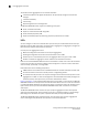
Table Of Contents
- Contents
- Figures
- Tables
- About This Document
- Introducing FCoE
- Using the CEE CLI
- In this chapter
- CEE CLI configuration guidelines and restrictions
- Using the CEE command line interface (CLI)
- CEE CLI RBAC permissions
- Accessing the CEE CLI through the console interface or through a Telnet session
- Accessing the CEE CLI from the Fabric OS shell
- Accessing CEE CLI command modes
- Using CEE CLI keyboard shortcuts
- Displaying CEE CLI commands and command syntax
- Using CEE CLI command completion
- CEE CLI command syntax conventions
- Using CEE CLI command output modifiers
- Configuring VLANs Using the CEE CLI
- In this chapter
- VLAN overview
- Ingress VLAN filtering
- VLAN configuration guidelines and restrictions
- Default VLAN configuration
- VLAN configuration procedures
- Enabling and disabling a CEE interface
- Configuring the MTU on a CEE interface
- Creating a VLAN interface
- Configuring a VLAN interface to forward FCoE traffic
- Configuring a CEE interface as a Layer 2 switch port
- Configuring a CEE interface as an access interface or a trunk interface
- Configuring VLAN classifier rules
- Configuring VLAN classifier groups
- Associating a VLAN classifier group to a CEE interface
- Clearing VLAN counter statistics
- Displaying VLAN information
- Configuring the MAC address table
- Configuring STP, RSTP, and MSTP using the CEE CLI
- In this chapter
- STP overview
- RSTP overview
- MSTP overview
- STP, RSTP, and MSTP configuration guidelines and restrictions
- Default STP, RSTP, and MSTP configuration
- STP, RSTP, and MSTP configuration procedures
- STP, RSTP, and MSTP-specific configuration procedures
- STP and RSTP-specific configuration procedures
- RSTP and MSTP-specific configuration procedures
- MSTP-specific configuration procedures
- 10-Gigabit Ethernet CEE interface-specific configuration
- Global STP, RSTP, and MSTP-related configuration procedures
- Clearing STP, RSTP, and MSTP-related information
- Displaying STP, RSTP, and MSTP-related information
- Configuring Link Aggregation using the CEE CLI
- Configuring LLDP using the CEE CLI
- Configuring ACLs using the CEE CLI
- In this chapter
- ACL overview
- Default ACL configuration
- ACL configuration guidelines and restrictions
- ACL configuration procedures
- Creating a standard MAC ACL and adding rules
- Creating an extended MAC ACL and adding rules
- Modifying a MAC ACL
- Removing a MAC ACL
- Reordering the sequence numbers in a MAC ACL
- Applying a MAC ACL to a CEE interface
- Applying a MAC ACL to a VLAN interface
- Clearing MAC ACL counters
- Displaying MAC ACL information
- Configuring QoS using the CEE CLI
- Configuring FCoE using the Fabric OS CLI
- Administering the switch
- Configuring RMON using the CEE CLI
- Index

72 Converged Enhanced Ethernet Administrator’s Guide
53-1001258-01
Default LACP configuration
5
• LACP enables the exchange of the system ID and administrative keys across member links to
directly-connected neighboring devices. Included in the information exchange is the following:
- Actor port/partner port.
- Actor system ID/partner system ID.
- Actor administrative key/partner administrative key.
- Actor state/partner state—Contained in both actor state and partner state are the
following: LACP activity, LACP timeout, aggregability, synchronization, collecting, and
distributing.
• Essentially all ports get aggregated if they have the following:
- The same actor system ID and actor administrative key.
- The same partner system ID and partner administrative key.
• LACP exchanges the aggregator states with its neighbors, which decide the rate at which the
LACPDU flow (slow or fast).
• After aggregation, a link can be part of a LAG but does not need to participate in the
distribution of traffic.
• When control protocols such as STP, RSTP, and MSTP see the deletion of a LAG or the addition
of a new LAG interface, they reevaluate the topology and determine the port state and port role
(root, designated, or blocked) based on BPDUs.
• Dynamically adding a new link to an existing LAG is done by configuring the existing LAG
administrative key (port-channel number) to the new link. LACP conveys this new link and its
administrative key to the neighbor. If the neighbor also decides to accept the new link, then the
link is associated to the existing local aggregator and LAG. The Layer 2 protocols see that the
physical link is now part of the LAG.
• Dynamically deleting a link from an existing LAG is done by removing the channel-group
configuration (no channel-group command) for the link to be deleted.
• Physical link failure—the physical failure of a link causes the removal of the link from the LAG.
Default LACP configuration
Table 12 lists the default LACP configuration.
TABLE 12 Default LACP configuration
Parameter Default setting
System priority 32768
Port priority 32768
Timeout Long (standard LAG) and short (Brocade LAG)