
Brocade Converged Enhanced Ethernet Administrator's Guide v6.1.2_cee (53-1001258-01, June 2009)
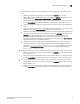

Table Of Contents
- Contents
- Figures
- Tables
- About This Document
- Introducing FCoE
- Using the CEE CLI
- In this chapter
- CEE CLI configuration guidelines and restrictions
- Using the CEE command line interface (CLI)
- CEE CLI RBAC permissions
- Accessing the CEE CLI through the console interface or through a Telnet session
- Accessing the CEE CLI from the Fabric OS shell
- Accessing CEE CLI command modes
- Using CEE CLI keyboard shortcuts
- Displaying CEE CLI commands and command syntax
- Using CEE CLI command completion
- CEE CLI command syntax conventions
- Using CEE CLI command output modifiers
- Configuring VLANs Using the CEE CLI
- In this chapter
- VLAN overview
- Ingress VLAN filtering
- VLAN configuration guidelines and restrictions
- Default VLAN configuration
- VLAN configuration procedures
- Enabling and disabling a CEE interface
- Configuring the MTU on a CEE interface
- Creating a VLAN interface
- Configuring a VLAN interface to forward FCoE traffic
- Configuring a CEE interface as a Layer 2 switch port
- Configuring a CEE interface as an access interface or a trunk interface
- Configuring VLAN classifier rules
- Configuring VLAN classifier groups
- Associating a VLAN classifier group to a CEE interface
- Clearing VLAN counter statistics
- Displaying VLAN information
- Configuring the MAC address table
- Configuring STP, RSTP, and MSTP using the CEE CLI
- In this chapter
- STP overview
- RSTP overview
- MSTP overview
- STP, RSTP, and MSTP configuration guidelines and restrictions
- Default STP, RSTP, and MSTP configuration
- STP, RSTP, and MSTP configuration procedures
- STP, RSTP, and MSTP-specific configuration procedures
- STP and RSTP-specific configuration procedures
- RSTP and MSTP-specific configuration procedures
- MSTP-specific configuration procedures
- 10-Gigabit Ethernet CEE interface-specific configuration
- Global STP, RSTP, and MSTP-related configuration procedures
- Clearing STP, RSTP, and MSTP-related information
- Displaying STP, RSTP, and MSTP-related information
- Configuring Link Aggregation using the CEE CLI
- Configuring LLDP using the CEE CLI
- Configuring ACLs using the CEE CLI
- In this chapter
- ACL overview
- Default ACL configuration
- ACL configuration guidelines and restrictions
- ACL configuration procedures
- Creating a standard MAC ACL and adding rules
- Creating an extended MAC ACL and adding rules
- Modifying a MAC ACL
- Removing a MAC ACL
- Reordering the sequence numbers in a MAC ACL
- Applying a MAC ACL to a CEE interface
- Applying a MAC ACL to a VLAN interface
- Clearing MAC ACL counters
- Displaying MAC ACL information
- Configuring QoS using the CEE CLI
- Configuring FCoE using the Fabric OS CLI
- Administering the switch
- Configuring RMON using the CEE CLI
- Index
Converged Enhanced Ethernet Administrator’s Guide 77
53-1001258-01
LACP troubleshooting tips
5
• If a Brocade-based dynamic trunk is configured on a link and the link is not able to join the
LAG:
- Make sure that both ends of the link are configured as Brocade for trunk type.
- Make sure that both ends of the link are not configured for passive mode. They must be
configured as either active/active, active/passive, or passive/active.
- Make sure that the port-channel interface is in the administrative “up” state by ensuring
that the no shutdown command was entered on the interface on both ends of the link.
- Make sure that the links that are part of the LAG are connected to the same neighboring
switch.
- Make sure that the system-id of the switches connected by the link is unique. This can be
verified by entering the show lacp sys-id command on both switches.
- Make sure that LACPDUs are being received and transmitted on both ends of the link and
there are no error PDUs. This can be verified by entering the show lacp port-channel-num
counters command and looking at the rx and tx statistics. The statistics should be
incrementing and should not be at zero or a fixed value. If the PDU rx count is not
incrementing, check the interface for possible CRC errors by entering the show interface
link-name command on the neighboring switch.
- Make sure that the fiber length of the link has a deskew value of 7 micro-seconds. If it
does not, the link will not be able to join the LAG and the following RASLOG message is
generated:
Deskew calculation failed for link <link-name>. When a link has this
problem, the show port port-channel link-name command displays the following:
Mux
machine state : Deskew not OK
.
• If a Brocade-based static trunk is configured on a link and the link is not able to join the LAG:
- Make sure that both ends of the link are configured as Brocade for trunk type and verify
that the mode is “on.”
- Make sure that the port-channel interface is in the administrative “up” state by ensuring
that the no shutdown command was entered on the interface on both ends of the link.
• If a standards-based static trunk is configured on a link and link is not able to join the LAG:
- Make sure that both ends of the link are configured as standard for trunk type and verify
that the mode is “on.”
- Make sure that the port-channel interface is in the administrative “up” state by ensuring
that the no shutdown command was entered on the interface on both ends of the link.