HP 3PAR StoreServ 10000 Storage Physical Planning Manual Abstract This manual provides information that is useful for planning and preparing for the installation of the HP 3PAR StoreServ Storage system. Use this document in conjunction with the HP 3PAR Systems Assurance and Pre-Installation Site Planning Guide that details specific system configuration and installation information for your storage system and operating site.
© Copyright 2011, 2014 Hewlett-Packard Development Company, L.P. The information contained herein is subject to change without notice. The only warranties for HP products and services are set forth in the express warranty statements accompanying such products and services. Nothing herein should be construed as constituting an additional warranty. HP shall not be liable for technical or editorial errors or omissions contained herein. Acknowledgments Microsoft® and Windows ®are U.S.
Contents 1 System Components and Specifications.........................................................5 HP 3PAR Storage System Components.........................................................................................5 StoreServ Storage Security Feature............................................................................................79 Enhancing Security with Data Encryption..............................................................................
TCP/IP Port Assignments..........................................................................................................65 Controller Node Connections...................................................................................................67 Required Cables.....................................................................................................................68 External Cable Connections..........................................................................................
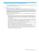
1 System Components and Specifications This chapter describes the system components and physical and capacity specifications for the HP 3PAR StoreServ 10000 Storage systems. HP 3PAR Storage System Components HP 3PAR Storage systems are designed around a cluster-based approach that incorporates sophisticated data management and fault tolerance technologies that can meet the storage needs of smaller sites and can easily be scaled for global organizations.
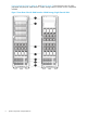
Figure 3 (page 8), Figure 1 (page 6), and Figure 2 (page 7) show the front views of a fully populated 2M (40U) HP 3PAR StoreServ 10000 Storage cabinet with the various components installed.
Figure 2 Front View of the HP 3PAR StoreServ 10000 Storage, 3–Phase PDU HP 3PAR Storage System Components 7
Figure 3 Front View of the HP 3PAR StoreServ 10000 Storage with 3PAR PDUs 8 System Components and Specifications
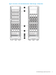
Figure 4 Rear View of the HP 3PAR StoreServ 10800 (left) and 10400 (right) Storage systems, 3PAR PDU HP 3PAR Storage System Components 9
For Figure 1 (page 6) and Figure 2 (page 7), use the following table: Item Description 1 Cable management tray 2 Drive chassis 3 Cooling fans 4 Battery modules 5 Service processor 6 PDUs 7 Leveling feet StoreServ Storage Security Feature The Data Encryption feature allows you to encrypt all specifically formatted hard drives on the storage system with an authentication key and the use of Self Encrypting Drives (SEDs).
Physical Specifications Table 1 Physical Specifications Physical Specifications 2M Cabinet Dimensions (width x height x depth) 23.6 x 76.5 x 36 in. 60 x 194.3 x 91.3 cm Service Clearance 36 in. (front) and 30 in. (rear) 91.44 cm (front) and 76.2 cm (rear) Weight (not populated) 439.8 lbs. 195.5 kg Maximum Weight (fully populated) 1,880 lbs. 852.8 kg Maximum Weight per leveling foot 470 lbs. 213.2 kg Maximum Load per leveling Foot 149.6 lbs./sq. in. 10.5 kg/sq.
Table 2 Storage Capacity Specifications (continued) Feature 10400 10800 2.3-1100 TB 2.3-2200 TB Architectural maximum number of drives 3,200 6,400 RAID levels RAID 0, 1, 5, 6, 10, 50 RAID 0, 1, 5, 6, 10, 50 RAID 5 data to parity ratios 2:1 - 8:1 2:1 - 8:1 Drive capacities (GB’s approx.)1 300GB 15k, 450GB, 600GB 15k, 300GB 15k, 450GB, 600GB 15k, 900GB, 1TB NL, 1.2TB SAS, 2TB NL, 900GB, 1TB NL, 1.2TB SAS, 2TB NL, 4TB NL 4TB NL Raw capacity (approx.
2 General Site Planning This chapter provides general recommendations for physical planning and site preparation for the installation and operation the storage system. General Planning Successful installation of HP 3PAR Storage systems requires careful planning and supervision in collaboration with authorized HP representatives. Proper planning will help provide for a more efficient installation and greater reliability, availability, and serviceability.
At installation time, the HP representative will supervise the delivery and unpacking of the equipment. The representative must also review the crate with the customer to check that the shipping crates have not been tampered with. When unpacking the equipment, verify the shipment is correct and all equipment is delivered. Refer to the packing slip and the SKUs with the shipment.
Figure 5 (page 15) shows the front view of the opened shipping container with ramps in place: Figure 5 Front View of the Cabinet Shipping Container When the equipment arrives, you must make sure that there is enough room to unload and unpack the storage system. The specific amount of space you will need is based on the dimensions of the container, the ramp and the room required to access the system so that it can be moved to its placement destination.
The specific amount of space you will need to unpack the server is based on the dimensions of the container, the ramp and the room required to access the server so that it can be moved to its placement destination. NOTE: See “Structural/Environmental Considerations” (page 17)“Providing for Service Access” (page 24) for more information on placing the storage systems and reserving room for service access.
3 Structural/Environmental Considerations Consider the following when choosing or designing your facilities for HP 3PAR Storage Systems: • Equipment location and layout that allows efficient use, easy maintenance, and future expansion. • Facility construction that provides a suitable operating environment, sufficient power and adequate protection from fire, contamination, or other hazards. • Suitable temperatures and appropriate air quality that is free from environmental contaminants.
Table 3 Raised Floor Specifications Specification Value Flatness tolerance - Per 10 ft (3 m) span Less than 0.06 in. (1.5 mm) Overall Less than 0 .10 in. (2.5 mm) Deflection - Dynamic Less than 0.15 in. (3.8 mm) Permanent Less than 0.02 in. (0.5 mm) Pedestal assembly load - Axial At least 5,000 lb (2,268 kg) Side At least 30 ft-lb (40.7 N-m) Placing each cabinet across two floor tiles is strongly recommended.
Before placing a cabinet on floor tiles shared with other cabinets or equipment, verify the floor panels can tolerate the weight and pressure loads. Maximum weight and pressure loads for storage systems are provided in Table 4 (page 19). When placing cabinets with their weight shared by the same panels as shown in Figure 8 (page 18), verify if each panel can tolerate the maximum weight calculation: Where cabinet x and cabinet y are cabinets or equipment resting partially on the same floor panel.
Figure 9 Tile Cutout Specifications for a Cabinet Resting on Two Floor Tiles 20 Structural/Environmental Considerations
Anchoring Dimensions for Storage Systems Some installations may prefer to anchor storage systems to the floor for better stability, especially in seismically active locations. While HP does not supply, or specifically recommend any particular anchoring solution, there are several third-party anchoring kits that can be procured for this purpose.
Figure 12 Bottom View Dimensions 22 Structural/Environmental Considerations
Additional Flooring Recommendations Consider the following recommendations for raised floor installations: • The flooring should be high enough to allow under the floor routing of cables and specified airflow to system air intakes. The recommended minimum floor clearance is 30.5 cm (12 in). An additional 7.6 cm (3 in) should be allowed for cables and connectors. A floor clearance of 46 cm (18 in) is recommended for new construction.
Figure 13 Hot-Aisle/Cold-Aisle Layout Form rows of racks or cabinets perpendicular to air conditioners. This formation facilitates an unobstructed flow of heated air down the aisles to the air conditioner return ducts. Heated air must not be forced to travel over or between the cabinets to get to the air conditioner return ducts. Doing so could heat the air in the cold aisles. Ensure that any free-standing equipment does not allow air to flow between the hot and cold aisles.
Table 5 Recommended Access Areas for HP 3PAR Cabinets Cabinet Surface Access Area During Operation Front 36 in (91.4 cm) Rear 30 in (76.2 cm) Left and right sides None NOTE: HP 3PAR cabinets do not require side access during operation. However, during installation, one side of the cabinet must be removed to access the PDU power cords.
listed in Table 7 (page 26) to estimate the cooling requirements for a storage system based on a specific system configuration. Proper site layout is critical to ensure the ambient temperature near the intake of the system does not rise beyond the system specifications. Exceeding the maximum ambient temperature for any period negatively affects the system’s reliability and performance, and continued operation for extended periods under such conditions might actually cause the system to shut down.
Air Cleanliness Air contaminants can cause equipment malfunction and can damage storage systems. It is essential that steps be taken to prevent air contaminants, such as metal particles, solvent vapors, corrosive gases, soot, airborne fibers, or salt, from entering or being generated within the server room environment. A high-efficiency air filter should be employed on each air inlet for outside air to stop dust at the point of entry to the installation site.
4 Power Requirements This chapter describes the general power requirements for the HP 3PAR StoreServ 10000 Storage. Storage System Power Distribution Units Each node has two dedicated power supplies and each drive chassis has four power supplies. The drive cages and controller nodes depend on these power supplies. The drive chassis power supply is located at the rear of the chassis while the node power supply is located behind the cable management tray in the node chassis.
Single-Phase HP Power Distribution Units The following configuration illustrates the power supplies within the power domains of a V800 system. The Single-Phase HP PDUs are physically different from HP 3PAR PDUs and all four are mounted at the bottom of the cabinet. See Figure 15 (page 29).
The following figure illustrates the numbering order of each PDU. See Figure 16 (page 30).
The following figure shows the location of the breakers and power banks of the Single-Phase HP PDU. See Figure 17 (page 31).
3-Phase HP Power Distribution Units The following configuration illustrates the power supplies within the power domains of a V800 system. The two 3-Phase HP PDUs are mounted at the bottom of the cabinet. See Figure 18 (page 32).
The following figure illustrates the numbering order of the mounted 3-Phase PDUs. See Figure 19 (page 33).
The following figure shows the location of the breakers and power banks of the 3-Phase PDU. See Figure 20 (page 34).
Single-Phase HP 3PAR Power Distribution Units The following configuration illustrates the power supplies within the power domains of a V800 system. The four Single-Phase HP 3PAR PDUs are mounted along the side of the cabinet. See Figure 21 (page 35).
The following figure illustrates the numbering order of the side-mounted PDUs. See Figure 22 (page 36).
Each PDU is equipped with separate power banks and separate circuit breakers, and are used exclusively for storage system components. Figure 23 Power Banks in the Single-Phase HP 3PAR PDU Battery Modules The HP 3PAR StoreServ 10000 Storage includes one or two battery compartments that hold up to four battery modules each. The battery compartment is part of the node chassis and adjacent to the node fan compartment (Figure 24 (page 38)).
Figure 24 Battery Modules Front View of Cabinet Power Cord Connections HP 3PAR Storage systems arrive with all internal power cords configured. Each PDU AC cord connects to the customer's power and supplies power to the node and drive chassis power supplies. As shown in Figure 25 (page 39), the power can be routed from the upper or lower access opening of the cabinet. Single Phase PDU systems have four cords while 3–Phase PDU systems have two.
Figure 25 Routing of the Main Power Cords, Single Phase and 3–Phase PDU Systems Item Description 1 Upper access opening 2 Lower access opening Cabinets with HP single-phase PDUs have 12 ft (3.66 m) main power cords. Cabinets with HP three-phase PDUs have 11 ft (3.35 m) main power cords. These are used with Product Numbers QW978A, QW979A, and QW982A. Cabinets with 3PAR PDUs have 14 ft (4.27 m) main power cords. These are used with Product Numbers QR584C, QR585C, QR632C, QR637C, QR596A, and QR639A.
the current requirements for a specific system configuration. For proper redundant power protection, power should be supplied from two or more power sources. Power and Heat Specifications NOTE: All measurements listed are based on testing conducted at 208 VAC. Table 8 Storage System Power Requirements 2 Meter Cabinet Max. Watts per Cabinet (fully populated) 9,9841 Max.
Table 8 Storage System Power Requirements (continued) BTU/hour (fully populated) 4487 3378 Drive Chassis (no magazines) Watts 200 BTU/hr 683 Drive Magazine 3 Transactional Idle Watts 9.8 5.5 BTU/hour 33 19 Watts 10.3 7 BTU/hour 35 24 Watts 14.8 8.8 BTU/hour 50 30 Watts 22 8.8 BTU/hour 74.8 30 Watts 20.8 8.0 BTU/hour 71 26.6 Watts 75 57 BTU/hour 256 195 Watts 32.4 19.2 BTU/hour 110.6 65.5 Watts 76 65 BTU/hour 258 222 Watts 34 19.
Table 8 Storage System Power Requirements (continued) Watts 62 38 BTU/hour 211 131 Watts 48 32 BTU/hour 163.8 109.7 Watts 48.8 35.6 BTU/hour 166.2 121.7 Watts 54 36.8 BTU/hour 184.5 121.
Voltage Spikes The HP 3PAR Storage systems are tested to comply with the EN 61000-45 standard. Installing a lightning protection device on the server room power source is recommended when the following conditions exist: • The primary power is supplied by an overhead power service. • The utility company installs lightning protectors on the primary power source. • The area is subject to electrical storms or an equivalent type of power surge.
Figure 26 Front View of the 10400 with Controller Nodes and Drive Chassis, Single-Phase HP PDU Systems 44 Power Requirements
Figure 27 Front View of the 10800 with the Controller Nodes and Drive Chassis, Single-Phase HP PDU Systems Redundant Power 45
Figure 28 Front View of the 10400 with 3-Phase HP PDU Systems 46 Power Requirements
Figure 29 Front View of the 10800 with 3-Phase HP PDU Systems Redundant Power 47
Figure 30 Rear View of the 10400 and 10800 with Single-Phase HP PDU Systems 48 Power Requirements
Figure 31 Rear View of the 10400 and 10800 with 3-Phase HP PDU Systems Redundant Power 49
Figure 32 Front View of the 10400 and 10800 Power Domains for the Controller Nodes and Drive Chassis, 3PAR PDU Systems 50 Power Requirements
Figure 33 Rear View of the 10400 (left) and 10800 (right) Power Domains within the Controller Nodes and Drive Chassis, 3PAR PDU Systems WARNING! To avoid possible injury, damage to storage system equipment, and potential loss of data, do not use the surplus power outlets in the storage system PDUs. Never use outlets in the PDUs to power components that do not belong to the storage system or to power storage system components that reside in other cabinets.
Figure 34 Redundant Power Cabling, 10400 Node Cabinet, 3PAR PDU Systems 52 Power Requirements
Figure 35 Redundant Power Cabling, 10400 Node Cabinet, Single Phase HP PDU Systems Redundant Power 53
NOTE: 54 The following describes the connection between the PDUs and power extension bars: • PDU 0 connects to power extension bar A1. • PDU 1 connects to power extension bar B1 and B2. • PDU 2 connects to power extension bar A3 and A4. • PDU 3 connects to power extension bar B3 and B4.
Figure 36 Redundant Power Cabling, 10400 Node Cabinet, 3–Phase PDU Systems NOTE: The following describes the connection between the PDUs and power extension bars: • PDU 0 connects to power extension bar A1 and A4. • PDU 1 connects to power extension bar B1 and B4.
Figure 37 Redundant Power Cabling, 10800 Node Cabinet, 3PAR PDU Systems 56 Power Requirements
Figure 38 Redundant Power Cabling, 10800 Node Cabinet, Single Phase HP PDU Systems Redundant Power 57
NOTE: 58 The following describes the connection between the PDUs and power extension bars: • PDU 0 connects to power extension bar A1. • PDU 1 connects to power extension bar B1 and B2. • PDU 2 connects to power extension bar A3 and A4. • PDU 3 connects to power extension bar B3 and B4.
Figure 39 Redundant Power Cabling, 10800 Node Cabinet, 3–Phase PDU Systems Redundant Power 59
Figure 40 Redundant Power Cabling, Expansion Node Cabinet, 3PAR PDU Systems 60 Power Requirements
Figure 41 Redundant Power Cabling, Expansion Node Cabinet, Single Phase HP PDU Systems Redundant Power 61
Figure 42 Redundant Power Cabling, Expansion Node Cabinet, 3–Phase PDU Systems 62 Power Requirements
5 Network, Cabling and Connectivity This chapter provides information on determining the best network configuration for the HP 3PAR Storage systems being installed at your site including the necessary connections and cable routing options. NOTE: The information that follows assumes an established network and discusses how to connect a storage system to that network.
Figure 43 Storage System and Service Processor on Shared Segment (Shared Topology) A shared topology requires: • A static IP address and system name for the storage system. • Two Ethernet connections from a switch or hub to the storage system controller nodes. • A static IP address for the SP. • One Ethernet connection from a switch or hub to the SP. • At least one management station on the network segment.
NOTE: This configuration does not permit the SP to communicate with the remote support center.
Table 9 TCP/IP Port Usage Table (continued) Port Usage 5782: 3PAR Management Service (unsecured) Used for storage system monitoring and configuration over an unsecured channel by the following components: Flow of Traffic • HP 3PAR OS Management Console • HP 3PAR OS CLI HP 3PAR IMC <--> HP 3PAR CLI Server • HP 3PAR Recovery Manager • HP 3PAR System Reporter • HP 3PAR Service Processor HP 3PAR CLI <--> HP 3PAR CLI Server (Port 2540 used prior to 2.2.4.
Table 9 TCP/IP Port Usage Table (continued) Port Usage 5989: WBEMCIM-XML (HTTPS) (secured) Used for storage server monitoring and configuration over a secured channel by the following component: Flow of Traffic HP 3PAR CIM Server 3rd Party CIM Client <--> HP 3PAR CIM Server Controller Node Connections The controller nodes provide the slots that are required to connect to external drives, systems and other devices. As shown in Figure 45 (page 67), a controller node contains nine PCI slots.
The number of ports available for the host connection will vary based on the configuration. Depending on the number of controller nodes in the system, the type of Fibre Channel adapters installed, and the method of drive chassis connection being used, an HP 3PAR StoreServ 10000 Storage can support a maximum of 2-48 drive chassis. Controller nodes can hold a maximum of nine PCI adapters.
Table 11 External Controller Node Connections (continued) Connection Type Minimum Configuration Recommended Configuration with connections distributed evenly across all nodes Maintenance 1 None Varies according to system and network configuration To provide redundancy and to permit online software upgrades, both controller nodes in a node pair (for example, nodes 0 and 1, nodes 2 and 3, and so on) must maintain connections to each host server.
Cable Routing Options Storage system cabinets have both upper and lower access openings available for Fibre Channel cable routing (Figure 46 (page 70)). It is also possible to route network cables and main power cords through specially designated upper and lower openings in the cabinet. NOTE: FC connections to expansion cabinets are routed at the REAR.
6 Third-Party Rack Mounting This chapter describes the available options and necessary requirements for installing HP 3PAR 10400 Storage components in third-party racks. Third Party Rack Mounting Considerations Some installations may want to use third-party cabinets to house the HP 3PAR Storage system components supplied by HP. Only install system components into a four-post rack. Two post-racks are not supported.
Location of Envisaged Rack 30 in. (76.2 cm) of service clearance is needed on both sides of the front of the cabinet. Required as two people must lift it into the cabinet, and space is needed on each side for the person to stand and maneuver the chassis. 30 in. (76.2 cm) of unobstructed clearance is needed directly behind the chassis to service the nodes (e.g., no PDUs, power-strips, power cord routing and other stuff attached to the back of their rack).
Node Chassis Installation Notes The shelf-rails it is mounted on should be no more than 30 inches from the floor. It becomes difficult to lift it above that height. To service the power supplies (located at the bottom and tucked under the nodes), there must be at least 1U (1.75 inches) of clearance below the chassis. For example, you could not have a DC4 Drive Chassis (MBOD) installed directly below it because you would not be able to service the node power supplies.
Figure 48 Required Dimensions for the DC4 Drive Chassis If you are installing the HP 3PAR equipment in a Four Post Cabinet, it must meet the minimum and maximum specifications shown in Figure 49 (page 74). Figure 49 Required Width and Depth Dimensions for a Four-Post Cabinet NOTE: When installing HP 3PAR equipment in a Four Post Cabinet, there must not be any obstructions to the installation of the rails and the chassis, and there must be a clear path between the front and rear vertical (RETMA) rails.
Rack Space Considerations HP highly recommends installing the node-chassis and all drive chassis in contiguous rack space. This is especially true for the initial installation as it ensures Fibre Channel cables will reach and provides consistency for servicing and installation. When adding additional drive chassis at a later date, it is desirable to place them with the initial chassis, but it is not required.
Figure 51 Spacing Dimensions of RETMA Rails Maintaining Minimum Clearances Proper clearances should be maintained for all third-party rack mounted installations to allow for proper ventilation, cabling and access for maintenance. Table 15 (page 76) shows the minimum clearance that should be maintained for third-party rack installations: Table 15 Minimum Clearances for Third-Party Racks Minimum Clearances Service Front: 36 in. (91.4 cm) Rear: 30 in. (76.2 cm) x 19 in. (50.
Figure 52 Minimum Clearances for Four-Post Racks 10400 Rack Mounting Kits Table 16 Mounting Racks and Kits Node Chassis Service Processor Cable Tray Kit Part Number 960-200105 Part Number 960-200106 Drive Chassis Part Number 960-200104 Four-Post Shelf Kit The four-post shelf kits allow the 10400 and DC4 drive chassis and components to be mounted in a variety of four-post racks and rack cabinets. Each chassis or component requires its own mounting kit.
Additionally, each line cord must be plugged into an outlet that is capable of supporting the entire load of its enclosure. CAUTION: In site planning, power distribution units are not provided with installation kit. Verify the PDUs belonging to the customer meet minimum power requirements before powering on the system. Special consideration must be given to this requirement.
7 StoreServ Storage Features StoreServ Storage Security Feature The Data Encryption feature allows you to encrypt all specifically formatted hard drives on the storage system with an authentication key and the use of Self Encrypting Drives (SEDs). Enhancing Security with Data Encryption When the system is licensed for Data Encryption, you must manually enable the encryption feature on the system.
8 Support and Other Resources Contacting HP For worldwide technical support information, see the HP support website: http://www.hp.
For information about: See: Migrating data from one HP 3PAR storage system to another HP 3PAR-to-3PAR Storage Peer Motion Guide Configuring the Secure Service Custodian server in order to monitor and control HP 3PAR storage systems HP 3PAR Secure Service Custodian Configuration Utility Reference Using the CLI to configure and manage HP 3PAR Remote Copy HP 3PAR Remote Copy Software User’s Guide Updating HP 3PAR operating systems HP 3PAR Upgrade Pre-Planning Guide Identifying storage system components
For information about: See: Planning for HP 3PAR storage system setup Hardware specifications, installation considerations, power requirements, networking options, and cabling information for HP 3PAR storage systems HP 3PAR 7200, 7400, and 7450 storage systems HP 3PAR StoreServ 7000 Storage Site Planning Manual HP 3PAR StoreServ 7450 Storage Site Planning Manual HP 3PAR 10000 storage systems HP 3PAR StoreServ 10000 Storage Physical Planning Manual HP 3PAR StoreServ 10000 Storage Third-Party Rack Physic
Typographic conventions Table 17 Document conventions Convention Element Bold text • Keys that you press • Text you typed into a GUI element, such as a text box • GUI elements that you click or select, such as menu items, buttons, and so on Monospace text • File and directory names • System output • Code • Commands, their arguments, and argument values • Code variables • Command variables Bold monospace text • Commands you enter into a command line interface • Syste
9 Documentation feedback HP is committed to providing documentation that meets your needs. To help us improve the documentation, send any errors, suggestions, or comments to Documentation Feedback (docsfeedback@hp.com). Include the document title and part number, version number, or the URL when submitting your feedback.
A Regulatory information For important safety, environmental, and regulatory information, see Safety and Compliance Information for Server, Storage, Power, Networking, and Rack Products, available at http:// www.hp.com/support/Safety-Compliance-EnterpriseProducts.