
HP 3PAR StoreServ 7450 Storage Service Guide

Node Removal
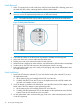
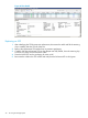
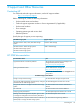
1. Allow 2-3 minutes for the node to halt, then verify the Node Status LED is flashing green and
the Node UID LED is blue, indicating that the node has been halted.
CAUTION: The system will not fail if the node is properly halted before removal but data
loss may occur if the replacement procedure is not followed correctly.
NOTE: The Node Fault LED may be amber, depending on the nature of the node failure.
Figure 36 Verify Node LED Status
NOTE:
2. Ensure that all cables on the failed node are marked to facilitate reconnecting later.
3. At the rear of the rack, remove cables from the failed node.
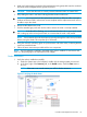
4. Pull the gray node rod to remove the node from the enclosure.
5. When the node is halfway out of the enclosure, use both hands to slide the node out completely.
6. Set the node on the ESD safe mat next to the replacement node for servicing.
7. Push in the failed node’s grey rod to ready it for packaging and provide differentiation from
the replacement node.
Node Installation
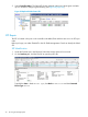
1. Move both SFPs from the onboard FC ports on the failed node to the onboard FC ports on
the replacement node:
a. Lift the retaining clip and carefully slide the SFP out of the slot.
b. Carefully slide the SFP into the FC port on the replacement node until fully seated and
close the wire handle to secure it in place.
2. If a PCIe adapter is installed in the failed node, move the SFPs from the PCIe adapter on the
failed node to the PCIe adapter on the replacement node:
a. Lift the retaining clip and carefully slide the SFP out of the slot.
b. Carefully slide the replacement SFP into the adapter on the replacement node until fully
seated. Close the wire handle to secure it in place.
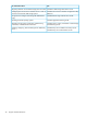
3. On the replacement node, ensure that the gray node rod is in the extracted position, pulled
out of the component.
32 Servicing the Storage System