HP 3PAR F-Class, T-Class, and StoreServ 10000 Storage Troubleshooting Guide for HP 3PAR OS 3.1.2 Abstract This guide is for system administrators and experienced users who are familiar with HP 3PAR F-Class, T-Class, and StoreServ 10000 Storage systems, understand the operating system(s) they are using, and have a working knowledge of RAID. This guide provides information on storage system alerts, components, LEDs and power on/off procedures.
© Copyright 2008, 2013 Hewlett-Packard Development Company, L.P. Confidential computer software. Valid license from HP required for possession, use or copying. Consistent with FAR 12.211 and 12.212, Commercial Computer Software, Computer Software Documentation, and Technical Data for Commercial Items are licensed to the U.S. Government under vendor's standard commercial license. The information contained herein is subject to change without notice.
Contents 1 Component Numbering for T-Class Storage System.........................................7 Identifying Storage System Components.....................................................................................34 Service Processor Placement.....................................................................................................37 Understanding Component Numbering.....................................................................................39 Cabinet Numbering..................
5 Understanding F-Class Storage System LED Status.........................................66 Using the F-Class Component LEDs............................................................................................66 Bezel LEDs........................................................................................................................66 Removing the Bezels and Unlocking the Door...................................................................67 Drive Chassis LEDs.............................
Cage Suggested Action 2............................................................................................103 Cage Example 3.........................................................................................................104 Cage Suggested Action 3............................................................................................104 Cage Example 4.........................................................................................................105 Cage Suggested Action 4.....
Format of Possible Port Exception Messages....................................................................119 Port Suggested Actions, General...................................................................................119 Port Example 1...........................................................................................................119 Port Suggested Action 1...............................................................................................119 Port Example 2...................
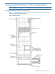
1 Component Numbering for T-Class Storage System NOTE: Illustrations in this chapter show sample systems and might not match your configuration. Identifying Storage System Components Figure 1 (page 7) and Figure 2 (page 8) identify the major components of the T400 Storage System in a 2M (40U) HP 3PAR cabinet.
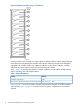
Figure 2 T400 Rear View Service Processor Placement The Service Processor (SP) is located at the bottom of the cabinet and is designed to support all actions required for maintenance of the storage system, providing real-time, automated monitoring. The SP also supports remote access to diagnose and resolve potential problems. The SP is usually installed directly above the PDUs and below the battery tray (Figure 3 (page 9)) and is powered internally by the storage system.
Figure 3 Placement of the SP NOTE: In the T800, the SP is located above the backplane, below the lowest drive chassis but above the upper battery tray. Figure 5 (page 11) illustrates SP placement for the T800. When a cabinet does not include a SP, a filler panel covers the area of the cabinet that the SP normally occupies.
Figure 4 Numbering of Chassis Bays in the Cabinet A storage system can be housed in a single cabinet or multiple cabinets. When multiple cabinets are required, the first cabinet (the controller node cabinet ) holds the storage system backplane populated with controller nodes. Any additional cabinets, or drive chassis cabinets , hold the additional drive chassis that do not fit into the controller node cabinet.
Figure 5 Controller Node Cabinet Component Layout Understanding Component Numbering 11
Figure 6 Drive Chassis Cabinet Component Layout PDU Numbering For each cabinet, the four Power Distribution Units (PDUs) occupy the lowest chassis bay in the cabinet. Numbers for PDUs are assigned: • beginning with 0. • from top to bottom. Figure 7 (page 12) illustrates the four PDUs at the bottom of a T-Class cabinet.
NOTE: In the T800, PDUs are positioned back-to-back so that they only take up 2U of space at the bottom of the cabinet rather than the standard 4U of space. PDUs are accessible from both the front and the rear of the storage system. “Controller Node Cabinet Component Layout” (page 11) illustrates PDU placement for the T800. Each PDU has two power banks, each with a separate circuit breaker, to be used exclusively for storage system components (Figure 8 (page 13)).
A battery tray can hold a maximum of four BBUs. The number of BBUs and battery trays in a system depends on the number of controller nodes installed (Table 2 (page 45)).
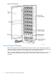
Figure 11 Magnetek BBU Numbering Scheme Controller Node Numbering The T-Class Storage System contain two, four, six, or eight controller nodes per system and only use T-Class controller nodes. Controller nodes are loaded into the backplane enclosure from bottom to top. Therefore, for the T800 with only two controller nodes installed, those controller nodes would occupy the lowest 4U of the backplane and would be numbered, node 6 and node 7.
Figure 12 Numbering of Controller Nodes As shown in Figure 13 (page 17), a controller node contains six PCI slots. These slots accept PCI adapters such as dual-port Fibre Channel adapters, iSCSI adapters, and Ethernet adapters. The controller node also has a management Ethernet port (E0) and a maintenance port (C1).
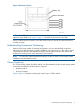
Figure 13 Numbering for Dual-Port Fibre Channel Adapters in the Controller Node PCI Slots Each Fibre Channel adapter in a PCI slot has four ports. Each iSCSI adapter in a PCI slot has two or four ports. PCI adapters assume the numbers of the PCI slots they occupy. • In dual-port adapters, ports are labeled port 1 and 2, from top to bottom. • In quad-port Fibre Channel adapters, the ports are numbered port 1–4, from top to bottom. Inside the controller node are control cache DIMMs and data cache DIMMs.
Figure 14 Control Cache and Data Cache DIMMs in a T-Class Controller Node Numbers for controller nodes and their components are assigned in the order indicated in Table 3 (page 18). Table 3 Numbering System for Controller Nodes and their Components The Following Components... Are Numbered... Running from...
Drive chassis are always placed above the storage system backplane enclosure and numbered according to their position in relation to the backplane, as shown in Figure 15 (page 49). Figure 15 Numbering of Drive Chassis NOTE: For systems occupying multiple cabinets, drive chassis numbers continue at the bottom of the next cabinet and progress through the top of the cabinet. Figure 16 (page 20) and Figure 17 (page 20) illustrate individual drive chassis components and how they are numbered.
Figure 16 Numbering of Drive Chassis Components Figure 17 Numbering of Disks on a DC4 and DC4 Type-2 Drive Magazine Numbers for drive chassis components are assigned: • from bottom to top. • from rear to front (in the case of disks). • in the order indicated by Table 4 (page 51). Table 4 Numbering System for Drive Chassis Components 20 The Following Components... Are Numbered... Running from... Drive cages 0,1,...
Table 4 Numbering System for Drive Chassis Components (continued) The Following Components... Are Numbered... Running from... Fibre Channel ports FC-AL 0 FC-AL 1 A0,B0 A1,B1 top to bottom Drive magazines 0,1,2,3,4,5,6,7,8,9 left to right Disks on the drive magazine 0,1,2,3 rear to front Drive Magazine Allocation For highest availability and data protection, drive magazines are placed on different loops and internal power domains by loading them in the order illustrated by Figure 18 (page 52).
NOTE: For further instructions on drive magazine allocation, see the HP 3PAR T-Class Storage System Installation and Deinstallation Guide . Power Supply Numbering Cabinets are divided into upper and lower power domains that contain drive cages or controller nodes and dedicated power supplies. Drive cages and controller nodes depend on these power supplies, located at the rear of the system, to supply power from the PDUs at the bottom of the cabinet.
2 Component Numbering for F-Class Storage System NOTE: Illustrations in this chapter show sample systems and might not match your configuration. Identifying Storage System Components Figure 20 (page 23) and Figure 21 (page 24) identify the major components of an F-Class Storage System.
Figure 21 F400 Rear View Service Processor Placement The Service Processor (SP) is located at the bottom of the cabinet and is designed to support all actions required for maintenance of the storage system, providing real-time automated monitoring. The SP also supports remote access to diagnose and resolve potential problems. Because the SP is capable of supporting multiple storage systems at the same operating site, not all cabinets contain a SP.
Understanding Component Numbering Because of the almost unlimited number of potential configurations, there is standardized component placement and internal cabling to simplify installation and maintenance. For this reason, system components are placed in the cabinet according to the principles outlined in this section and numbered according to their order and location in the cabinet. Cabinet Numbering The F-Class Storage System 2M (40U) cabinet is an EIA-standard rack that holds storage system components.
Table 5 (page 26) describes the pattern for cabinet numbering in multi-cabinet storage systems and for operating sites with multiple systems: Table 5 Cabinet Numbering Cabinet Number Controller node cabinet C00 Drive chassis cabinets connecting to the first node cabinet C01, C02, C03...C09 Figure 23 (page 26) shows the location of controller node and drive chassis components for the storage system cabinet in the F200 and F400.
Figure 24 Numbering of PDUs Each PDU has two power banks, each with a separate circuit breaker, to be used exclusively for storage system components (Figure 25 (page 27)). Figure 25 PDU Power Banks WARNING! To avoid possible injury, damage to storage system equipment, and potential loss of data, do not use the surplus power outlets in the storage system PDUs.
Figure 26 Numbering of Controller Nodes A controller node contains two controller slots and two on-board Ethernet ports. See Figure 27 (page 29) for specific port type assignments.
Figure 27 Numbering for Dual-Port Fibre Channel Adapters in the Controller Node PCI Slots Each Fibre Channel adapter in a PCI slot has two or four Fibre Channel ports. Fibre Channel adapters assume the numbers of the PCI slots they occupy. • In dual-port adapters, ports are labeled port 1 and port 2, from top to bottom. • In quad-port Fibre Channel adapters, the ports are numbered port 1, port 2, port 3, and port 4, horizontally. Inside the controller node are data cache DIMMs and control cache DIMMs.
Drive Chassis Numbering Depending on configuration, an F-Class Storage System can include up to 10 drive chassis. A drive chassis houses 16 drive magazines. Drive chassis are first placed sequentially below controller node 1 (controller node 3 in an F400) and then sequentially above controller node 0. Drive chassis are numbered as shown in Figure 29 (page 30).
Figure 30 Drive Chassis - Front View, Drive Magazine Bay Numbering Figure 31 Drive Chassis - Rear View, Port Numbering Drive Magazine Allocation For highest availability and data protection, drive magazines are placed on different loops and internal power domains by loading them in the order described in by Table 6 (page 32).
Table 6 Drive Magazine Loading Pattern Group Number Drive Magazine Pair Number Drive Magazine Bay 1 1 0, 4 2 11, 15 3 8, 12 4 3, 7 5 1, 5 6 10, 14 7 9, 13 8 2, 6 2 3 4 NOTE: The loading sequence displayed in the table above indicates the loading order is in vertical columns. All drives in a vertical column must be of the same type and speed. Mixing drive types and speeds in the same column may cause unpredictable results.
Figure 33 Numbering of Power Supplies Understanding Component Numbering 33
3 Component Numbering for HP 3PAR StoreServ 10000 Storage NOTE: Illustrations in this chapter only display examples of systems and may not match any particular storage system configuration. Identifying Storage System Components Figure 34 (page 34) through Figure 37 (page 37) identify major components of an HP 3PAR StoreServ 10000 Storage in a 2M cabinet.
Figure 35 Front View of HP 3PAR StoreServ 10400 and 10800 Storage Systems, Single Phase PDU Identifying Storage System Components 35
Figure 36 Front View of HP 3PAR StoreServ 10400 and 10800 Storage Systems, 3–Phase PDU 36 Component Numbering for HP 3PAR StoreServ 10000 Storage
Figure 37 Rear View of HP 3PAR StoreServ 10400 and 10800 Storage Systems, 3PAR PDU Service Processor Placement The Service Processor (SP) supports all actions required for the maintenance of the storage system. The SP provides real-time, automated monitoring of the storage system. The SP also supports remote access for HP to diagnose and resolve potential problems. The SP is adjacent to the controller node chassis and resides in the lower section of the cabinet or third-party rack.
Figure 38 Placement of the SP, 3PAR PDU Systems Figure 39 Placement of the Service Processor, Single Phase PDU Systems 38 Component Numbering for HP 3PAR StoreServ 10000 Storage
Figure 40 Placement of the Service Processor, 3–Phase PDU Systems NOTE: For both 10400 and 10800 Storage systems, the SP is located below the controller node chassis (Figure 38 (page 38), “Placement of the Service Processor, Single Phase PDU Systems” (page 38) and “Placement of the Service Processor, 3–Phase PDU Systems” (page 39)).
Figure 41 (page 40), Figure 42 (page 41), and Figure 43 (page 41) illustrate the PDUs in the HP 3PAR StoreServ 10000 Storage cabinet.
Figure 42 Power Distribution Units, Single Phase PDU Item Description 1 PDU #3 2 PDU #2 3 PDU #1 4 PDU #0 Figure 43 Power Distribution Units, 3–Phase PDU Item Description 1 PDU #2 2 PDU #1 Each PDU is equipped with separate power banks and separate circuit breakers, used exclusively for storage system components.
Figure 44 Power Banks in the PDU, 3PAR PDU Figure 45 Power Banks in the PDU, Single Phase PDU 42 Item Description 1 Front of unit, main breaker 2 Front of unit, circuit breakers 3 Rear of unit, power banks Component Numbering for HP 3PAR StoreServ 10000 Storage
Figure 46 Power Banks in the PDU, 3–Phase PDU Item Description 1 Front of unit, circuit breakers 2 Rear of unit, power banks WARNING! To avoid possible injury, damage to storage system equipment, and potential loss of data, do not use the surplus power outlets in the storage server PDUs. Never use outlets in the PDUs to power components that do not belong to the storage server or to power storage server components that reside in other cabinets.
Table 8 Fan Module Configuration Based Upon System and Number of Controller Nodes System Controller Nodes Fan Modules 10400 2 4 4 8 2 4 4 8 6 12 8 16 10800 The illustration explains the numbering scheme for the fan modules within a controller node. Figure 48 Fan Module Numbering Scheme, Single Phase and 3–Phase PDU Battery Module Numbering Depending on the controller node configuration, the controller node chassis may include one or two battery compartments to situate the battery modules.
Figure 49 Battery Module Battery module placement may vary according to the type of system configuration and number of installed controller nodes (Table 2 (page 45)).
Figure 50 Battery Module Numbering Scheme, 3PAR PDU Systems Figure 51 Battery Module Numbering Scheme, Single Phase and 3–Phase PDU 46 Component Numbering for HP 3PAR StoreServ 10000 Storage
Controller Node Numbering A storage system may contain two to eight controller nodes per system configuration. The controller node chassis is located at the rear of the storage cabinet. From the rear of the storage cabinet, component numbering starts with zero (0) from left to right. For example, the node in the lower left position is identified as Node 0 and the adjacent node (right) is identifed as Node 1.
As shown in Figure 53 (page 48), a controller node contains nine PCI slots. The following slots connect PCI adapters such as quad-port Fibre Channel Adapters and Converged Network Adapters (CNA). Each controller node features a main administrative Ethernet port (E0), Remote Copy Ethernet port (RCIP) (E1), and a console maintenance port (S0).
Figure 54 Numbering of Drive Chassis, 3PAR PDU Systems Understanding Component Numbering 49
Figure 55 Numbering of Drive Chassis, Single Phase and 3–Phase PDU NOTE: For systems with multiple cabinets, drive chassis numbering may vary. Figure 56 (page 50) and Figure 57 (page 51) illustrate individual drive chassis components and the numbering scheme. The Fibre Channel ports in the FC-AL adapters located on each side of the drive chassis enable connection to the controller nodes.
Figure 57 Numbering of Disks on a Drive Magazine Numbers for drive chassis components are assigned: • From bottom to top. • From rear to front (in reference of disks). • In the order indicated by Table 4 (page 51). Table 11 Numbering System for Drive Chassis Components The Following Components... Are Numbered... Running from... Drive cages 0,1,...
Figure 58 Pattern for Loading Initial Drive Magazines Into the Drive Chassis Power Supply Numbering Cabinets are divided into lower and upper power domains containing drive cages or controller nodes with dedicated power supplies. The drive cages and controller nodes depend on the power supplies located at the rear of the system to supply power from the PDUs.
Figure 59 Numbering of Power Supplies Within the Power Domains, Single Phase PDU Systems Understanding Component Numbering 53
Figure 60 Numbering of Power Supplies Within the Power Domains, 3–Phase PDU Systems Use the following table for Figure 59 (page 53) and Figure 60 (page 54): 54 Item Description 1 DC Power Supplies 2 Node Power Supplies 3 Node Power Supplies 4 DC Power Supplies 5 Power Distribution Units (PDU) Component Numbering for HP 3PAR StoreServ 10000 Storage
4 Understanding T-Class Storage System LED Status Using the T-Class Component LEDs The T-Class Storage System components have LEDs to indicate whether or not the hardware is functioning properly and to help identify errors. These LEDs help diagnose basic hardware problems. You can quickly identify hardware problems by examining the LEDs on all the components and using the following tables and illustrations in this chapter.
Figure 62 Connections and LEDs on the DC4 Drive Cage FC-AL Modules Table 12 Drive Cage DC4 FC-AL Module LED Displays LED Appearance Indicates RX Steady green light The presence of a small form-factor pluggable optical transceiver (SFP) and a valid signal from the node. No light No connection to the node or no SFP is installed. Steady green light The presence of an SFP and the LED is on and transmitting. No light No SFP is present or the SFP transmitter failed.
Table 12 Drive Cage DC4 FC-AL Module LED Displays (continued) LED Appearance Indicates high-level threshold, or a power supply has failed. Hot plug Split mode 4GB/s Flashing amber light (1 blink per second) The drive cage has some type of error, such as a failed or missing power supply, but is communicating with a node. Rapid toggle between amber and green light A cage firmware upgrade initiated by the upgradecage CLI command is in progress.
Figure 63 DC4 Drive Magazine LEDs Table 13 Drive Magazine LED Displays LED Appearance Indicates Drive magazine status Steady green light The drive magazine is functioning properly. Steady amber light A drive magazine error, or one or more drives are bypassed on at least one path. Disk status Hot plug 58 Quick flashing, or 20 percent on, 80 The disk is not spun up but has power. percent off green light Steady green light The disk is spun up and waiting for a command.
Controller Node LEDs Depending on configuration, storage systsem contain between two and eight controller nodes, all located in the chassis. Controller nodes contain the following LEDs (Figure 64 (page 59)): Figure 64 Controller Node LEDs Table 14 Controller Node LED Displays LED Appearance Indicates Disk hot plug Steady amber light Disk is prepared for hot plug. No light Disk is not prepared for hot plug.
Table 14 Controller Node LED Displays (continued) LED Ethernet status Appearance Indicates Flashing green light No Ethernet activity. No light No Ethernet connection. Steady amber light 1000 MB/s mode Steady green light 100 MB/s mode No light 10 MB/s mode (or disconnected) Fibre Channel Port LEDs The Fibre Channel adapter in the controller node also contains Fibre Channel port LEDs (Figure 65 (page 60)).
Figure 66 iSCSI Adapter Ports and LEDs Table 16 iSCSI Adapter Port LED Displays LED Appearance Indicates Port 1, 2 No light No connection or active link. Steady green light Link is established. Flashing green light Recieving or transmitting activity.
Figure 67 Power Supply LEDs NOTE: The appearance of the drive chassis and controller node power supplies can vary slightly according to manufacturer and location. Table 17 Power Supply LED Displays LED Appearance Indicates Power supply status Steady green light Power is on. Steady amber light Power supply error. No light Broken connection. Steady green light AC is entering from an external source.
Battery Backup Unit LEDs Depending on the configuration, storage systems with HP 3PAR cabinets include one or more battery trays that hold up to four BBUs each. BBUs supply power to write the cache memory to the drive inside the node in the event of a power failure.
Supermicro Service Processor LEDs Supermicro LEDs are located at the top of the SP. Figure 70 Supermicro SP LEDs Table 19 Supermicro SP LEDs LED Appearance Indicates Power No light SP is off. Steady green light SP is on. No light No hard drive activity. Flashing amber light Hard drive activity. No light Port is not connected. Steady green light Port is connected. Flashing green light Network activity. No light SP temperature is normal. Steady red light SP temperature is overheating.
Figure 71 Supermicro II SP LEDs Table 20 Supermicro II SP LEDs LED Appearance Indicates Power No light SP is off. Steady green light SP is on. No light No hard drive activity. Flashing amber light Hard drive activity. No light Port is not connected. Steady green light Port is connected. Flashing green light Network activity. No light SP temperature is normal. Steady red light SP temperature is overheating. Flashing red light SP has a failed fan.
5 Understanding F-Class Storage System LED Status Using the F-Class Component LEDs The F-Class Storage System components have LEDs to indicate whether or not the hardware is functioning properly and to help identify errors. These LEDs help diagnose basic hardware problems. You can quickly identify hardware problems by examining the LEDs on all the components and using the following tables and illustrations in this chapter.
Table 21 Bezel LED Displays (continued) LED Appearance Indicates Steady amber light Error within the node. Steady amber and hot-plug LED amber Fatal node failure. (see Controller Node LEDs on page 5.13) Removing the Bezels and Unlocking the Door If your HP 3PAR cabinet has locking fascias, you must first remove the fascias to access the system bezel. WARNING! Hazardous energy is located behind the rear access door of the storage system cabinet. Use caution when working with the door open.
Figure 74 Drive Chassis OPs Panel LEDs 68 Understanding F-Class Storage System LED Status
Table 22 Drive Chassis OPs Panel LED Displays LED Appearance Indicates Power On Steady green light Used in conjunction with Power Supply/Cooling/Temperature Fault LED, 2GB Link Speed LED, Invalid Address LED, and System Fault LED as described below. Power Steady amber light Supply/Cooling/Temperature Fault LED • Test state (5 seconds), if: ◦ Power On LED is steady green. ◦ System Fault LED is steady amber. ◦ Invalid Address LED is steady amber. ◦ 2GB Link Speed LED is steady green.
Table 22 Drive Chassis OPs Panel LED Displays (continued) LED Appearance Indicates Invalid Address LED Steady amber light • Indicates test state (5 seconds), if: System Fault LED ◦ Power On LED is steady green. ◦ Power Supply/Cooling/Temperature Fault LED is steady amber. ◦ System Fault LED is steady amber. ◦ 2GB Link Speed LED is steady amber. Flashing amber light Invalid address mode ID switch setting if Power On LED is steady green.
Interface Card LEDs The drive chassis contains two interface cards, FC-AL-A and FC-AL-B, with the following LEDs: Figure 75 Interface Card LEDs Table 23 Interface Card LED Displays LED Appearance Indicates Host Port 0, 1, 2, 3 Steady green light The incoming Fibre Channel signal is good. Steady green light All device ports are good at 2GB. No light All device ports are good at 1GB. Flashing green light Drives are bypassed by module. Steady amber light FC-AL module is failed.
Figure 76 Drive Chassis Power Supply/Cooling Module LEDs Table 24 Power Supply/Cooling Module LED Displays LED Appearance Indicates Power Supply Good Steady green light The power supply is operating normally. Steady amber light The power supply is not operating correctly. Steady green light Indicates the AC input is normal. Steady amber light Indicates AC input failure. Steady green light Indicates the fan is operating normally. Steady amber light There is a fan fault.
Figure 77 Drive Magazine LEDs Table 25 Drive Magazine LED Displays LED Appearance Indicates Activity Steady green light Drive power is present. Blinking green light There is drive activity. Slowly blinking green light (once every 3 seconds) The drive has spun down. No light A drive is not present. Steady amber light There is a drive fault. No light No drive is present. Drive power is on. Drive activity.
Figure 78 Controller Node LEDs Table 26 Controller Node LED Displays LED Appearance Indicates Disk hot plug Steady amber light Disk is prepared for hot plug. No light Disk is not prepared for hot plug. Steady amber light In combination with the status LED blinking green three times per second, indicates the node is prepared for removal. In combination with the status LED being solid, indicates a fatal failure. No light The node is not prepared for removal.
Table 26 Controller Node LED Displays (continued) LED Appearance Indicates Steady green light 100 MB/s mode No light 10 MB/s mode (or disconnected) Fibre Channel Port LEDs The Fibre Channel adapter in the controller node also contains Fibre Channel port LEDs: Figure 79 4-Port Fibre Channel LEDs Table 27 Fibre Channel Adapter LED Displays LED Appearance Indicates No light Wake up failure (dead device) Steady green light Normal - link up at 2-4GBs/s Flashing green light Link down or not connect
Table 28 iSCSI Adapter Port LED Displays LED Appearance Indicates No light No connection or active link. Steady green light Link is established. Flashing green light Recieving or transmitting activity. Emulex Fibre Channel Port LEDs The Emulex Fibre Channel adapter in the controller node also contain Fibre Channel port LEDs. Two port Emulex Fibre Channel adapters are only used in an F-Class Storage System (Figure 81 (page 76)).
Controller Node Power Supply LEDs F-Class Storage System controller node power supply units are located on both sides of the controller nodes. The battery is integral to the controller node power supply. The LEDs are located on the rear of the power supply units: Figure 82 Controller Node Power Supply LEDs Table 30 Power Supply LED Displays LED Appearance Indicates Power supply status Steady green light Power is on. Steady amber light Power supply error.
A blue illuminated lamp denotes that power is being supplied to a power bank. When the blue lamp is not illuminated, the power bank is not receiving AC input. Service Processor LEDs There are two types of service processors. Supermicro Service Processor The Supermicro SP LEDs are located at the top of the SP (Figure 84 (page 78)). Figure 84 Supermicro SP LEDs Table 31 Supermicro SP LED Displays LED Appearance Indicates Power No light SP is off. Steady green light SP is on.
Figure 85 Supermicro II SP LEDs Table 32 Supermicro II SP LED Displays LED Appearance Indicates Power No light SP is off. Steady green light SP is on. No light No hard drive activity. Flashing amber light Hard drive activity. No light Port is not connected. Steady green light Port is connected. Flashing green light Network activity. No light SP temperature is normal. Steady red light SP temperature is overheating. Flashing red light SP has a failed fan.
6 Understanding HP 3PAR StoreServ 10000 Storage LED Status The storage system components have LEDs to indicate whether or not the hardware is functioning properly and to help identify errors. The LEDs help diagnose basic hardware problems. You can quickly identify hardware problems by examining the LEDs on all of the components and using the tables and illustrations in this chapter. If you detect any problems during inspection of the LEDs, contact your Authorized Service Provider.
DC4 Drive Cage FC-AL Module LEDs The DC4 drive cage FC-AL modules have the following LEDs: Figure 87 FC-AL LED and Port Locations Table 33 Drive Cage DC4 FC-AL Module LEDs LED Appearance Indicates RX Steady green light A presence of a small form-factor pluggable optical transceiver (SFP) and a valid signal from the node. No light No connection to the node or no SFP is installed. Steady green light A presence of an SFP and that the LED is on and transmitting.
Table 33 Drive Cage DC4 FC-AL Module LEDs (continued) LED Appearance Indicates FC-AL module error or other cage error. If both FC-AL modules have a steady light, the temperature of a disk drive in the drive-cage has exceeded its high-level threshold, or a power supply has failed. Hot plug 4GB/s 82 Flashing amber light (1 blink per second) The drive cage has some type of error, such as a failed or missing power supply, but is communicating with a node.
Drive Magazine LEDs NOTE: After powering on, allow approximately two minutes for the disks on the drive magazine to spin up before checking the drive magazine LEDs. Drive magazines have the following LEDs: Figure 88 Drive Magazine LEDs Table 34 Drive Magazine LEDs LED Appearance Indicates Drive magazine status Steady green light The drive magazine is functioning properly. Steady amber light A drive magazine error, or one or more drives are bypassed on at least one path.
Controller Node LEDs Depending on configuration, storage systems contain between two and eight controller nodes, all located in the chassis. Controller nodes have the following LEDs: NOTE: You can issue the locatenode command to flash all service LEDs associated to a controller node blue. This includes the power supplies, battery modules, and fan module LEDs. Table 35 Controller Node LEDs LED Appearance Indicates Node Disk No light Normal operation.
Table 35 Controller Node LEDs (continued) LED HBA Service Appearance Indicates Rapidly flashing green light (three times per second) The node is booting, or, in combination with a blue service LED, the node is safe to remove. Flashing amber light The node has joined the cluster but there is a degraded component associated with the node. A slow flashing light means the node is part of the cluster. Steady amber light An error within the node.
Fan Module LEDs The 10400 controller node chassis can hold up to eight fan modules that each hold two fans, and the 10800 can hold up to 16. Fan modules have the following LEDs: Table 36 Fan Module LEDs LED Appearance Indicates Status Green Normal operation, no faults. Amber Fan speed is too low, failed, off or not working properly. With a blue service LED, the fan module failed and was not able to recover in 60 seconds. Replace the fan module. Solid Blue The servicenode start fan has been issued.
Fibre Channel Adapter Port LEDs The Fibre Channel adapter in the controller node also contains Fibre Channel port LEDs: Figure 90 Fibre Channel LEDs Table 37 Fibre Channel Adapter LEDs LED Appearance Indicates Port 1-4 No light Wake up failure (dead device) or power is not applied. (Port speed) Amber light off Not connected. Amber (3 fast blinks) Connected at 4GB/sec. Amber (4 fast blinks) Connected at 8GB/sec. Steady green light Normal/Connected - link up.
CNA Port LEDs The Converged Network Adapter (CNA) includes two ports with corresponding LEDs: Figure 91 CNA Port LEDs Table 38 CNA Port LEDs LED Appearance Indicates Link No light Link down Steady green light Link up No light No activity.
Ethernet LEDs The controller node has two built-in Ethernet ports and each port contains two LEDs: Figure 92 Ethernet LEDs Table 39 Ethernet LEDs LED Appearance Indicates ACT/LNK (top E0, E1) Steady green light Valid link partner Flashing green light Data activity No light ACT/LNK is off Steady yellow light 1000Mb/sec mode Steady green light 100Mb/sec mode No light 10Mb/sec mode Speed (bottom E0, E1) Ethernet LEDs 89
Power Supply LEDs Power supplies are located at the rear of the storage system. The drive chassis and controller node power supplies have the following LEDs: Drive Chassis Power Supply LEDs Drive chassis power supplies are located at the rear of the drive chassis. Figure 93 Drive Chassis Power Supply LEDs Table 40 Drive Chassis Power Supply LEDs LED Appearance Indicates Power Supply Status Steady green light Power is on. Steady amber light Power supply error. No light Broken connection.
Controller Node Power Supply LEDs The controller node power supplies are located behind the cable management tray in the node chassis. Figure 94 Controller Node Power Supply LEDs The power supply service LED is located on the dividers between the power supplies. Figure 95 Controller Node Power Supply Service LED Table 41 Controller Node Power Supply LEDs LED Appearance Indicates Power Status Steady green light Power is on. Steady amber light Power supply error. No light Broken connection.
Battery Module LEDs Depending on configuration, storage systems include one or two battery compartments that hold up to four battery modules each. Each node has one battery module. Each battery module has three LEDs: Figure 96 Battery Module LEDs Table 42 Battery Module LEDs LED Appearance Indicates Charging Green Battery modules is being charged. Amber Battery module is at fault. Off Battery module is not in node or connected. Green Battery module output is on and supplying power to the node.
Service Processor LEDs There are two types of SPs. Supermicro II Service Processor The Supermicro II LEDs are located at the front of the SP: Figure 97 Supermicro II SP LEDs Table 43 Supermicro II SP LEDs LED Appearance Indicates Power No light SP is off. Steady green light SPis on. No light No hard drive activity. Flashing amber light Hard drive activity. No light Port is not connected. Steady green light Port is connected. Flashing green light Network activity.
Figure 98 Front panel LEDs Table 44 Front panel LEDs Item LED Appearance Description 1 UID LED/button Blue Active Flashing Blue System is being managed remotely Off Deactivated Green System is on Flashing Green Waiting for power Amber System is on standby, power still on Off Power cord is not attached or power supplied has failed Green System is on and system health is normal Flashing Amber System health is degraded Flashing Red System health is critical Off System power is off
Table 45 Rear panel LEDs Item LED Appearance Description 1 NIC link Green Link Off No link Green or Flashing Green Activity Off No activity Blue Active Flashing Blue System is being managed remotely Off Deactivated Green Normal 2 3 4 NIC status UID LED/button Power supply NOTE: May not be applicable to Off your system (for hot-plug HP CS power supplies ONLY) Off = one or more of the following conditions: • Power is unavailable • Power supply has failed • Power supply is in stand
7 Power Off/On the Storage System The following describes the procedures for powering off and on the storage system. Powering Off the Storage System When it is necessary to power off the storage system, use the following steps to safely remove power from the storage system and the SP. NOTE: PDUs in any expansion cabinets connected to the storage system may need to be shut off. Use the locatesys command to identify all connected cabinets. locatesys will blink all node and drive cage LEDs.
1. 2. 3. Turn on AC power to the cabinet(s) by turning on all of the PDU circuit breakers. Verify that the blue LED on the front of the SP is illuminated. Verify that all drive chassis LEDs are solid green and all controller node status LEDs are blinking green once per second.
8 Alerts Alerts are triggered by events that require intervention by the system administrator. This chapter provides a list of alerts identified by message code, the message(s), and what action should be taken for each alert. To learn more about alerts, see the HP 3PAR OS Concepts Guide. For information about system alerts, go to http://www.hp.com/support/hpgt/3par and select your server platform. To view the alerts, use the showalert command.
9 Troubleshooting The HP 3PAR OS CLI checkhealth command checks and displays the status of storage system hardware and software components. For example, the checkhealth command can check for unresolved system alerts, display issues with hardware components or display information about virtual volumes that are not optimal. By default the checkhealth command checks most storage system components, but you can also check the status of specific components.
Checking snmp Checking task Checking vlun Checking vv Component -----------Description----------- Qty Alert New alerts 4 Date Date is not the same on all nodes 1 LD LDs not mapped to a volume 2 License Golden License.
Table 47 Component Functions Component Function Alert Displays any unresolved alerts. Cage Displays drive cage conditions that are not optimal. Date Displays if nodes have different dates. LD Displays LDs that are not optimal. License Displays license violations. Network Displays Ethernet issues. Node Displays node conditions that are not optimal. PD Displays PDs with states or conditions that are not optimal. Port Displays port connection issues. RC Displays Remote Copy issues.
• power supplies • cage firmware (is not current) Reports if a servicecage operation has been started and has not ended.
-----------Midplane Info----------Firmware_status Current Product_Rev 2.37 State Normal Op Loop_Split 0 VendorId,ProductId 3PARdata,DC4 Unique_ID 1062030000098E00 ...
-----------Cage detail info for cage1 --------Interface Board Info FCAL0 FCAL1 Link A RXLEDs Green Off Link A TXLEDs Green Off Link B RXLEDs Off Green Link B TXLEDs Off Green LED(Loop_Split) Off Off LEDS(system,hotplug) Amber,Off Amber,Off -----------Midplane Info----------Firmware_status Current Product_Rev 2.
cli% showpd Id CagePos 20 1:0:0 21 1:0:1 22 1:0:2 23 1:0:3 -s Type FC FC FC FC -State-degraded degraded degraded degraded -----Detailed_State-----disabled_B_port,servicing disabled_B_port,servicing disabled_B_port,servicing disabled_B_port,servicing cli% showpd -p -cg 1 Id 20 21 22 23 CagePos 1:0:0 1:0:1 1:0:2 1:0:3 Type Speed(K) State FC 10 degraded FC 10 degraded FC 10 degraded FC 10 degraded ---Size(MB)---Total Free 139520 119808 139520 122112 139520 119552 139520 122368 ----Ports---A B 0:0:2* 1:
Cage Example 5 Component -Identifier- ------------Description-----------Cage cage:4 Interface Card 0, SFP 0 is unqualified Cage Suggested Action 5 In this example, a 2Gb/sec SFP was installed in a 4Gb/sec drive cage (DC4), and the 2Gb SFP is not qualified for use in this drive cage. For cage problems, the following CLI commands are helpful: showcage -d, showcage -sfp, showcage -sfp -ddm, showcage -sfp -d, and showpd -state. cli% showcage -d cage4 Id Name LoopA Pos.A LoopB Pos.
Qualified TX Disable TX Fault RX Loss RX Power Low DDM Support : : : : : : Yes No No No No Yes Date Checks the date and time on all nodes and reports an error if they are not the same. Format of Possible Date Exception Messages Date -- "Date is not the same on all nodes" Date Example Component -Identifier- -----------Description----------Date -Date is not the same on all nodes Date Suggested Action The time on the nodes should stay synchronized whether there is an NTP server or not.
Format of Possible LD Exception Messages LD LD LD LD ld: ld: ld: ld: "LD "LD "LD "LD is not mapped to a volume" is in write-through mode" has preserved RAID sets and preserved chunklets" has reduced availability.
usually due to a node-down condition, when node batteries are not working, or where disk redundancy is not optimal. cli% showld Ten* Id Name RAID -Detailed_State- Own SizeMB UsedMB Use Lgct LgId WThru MapV 91 Ten.usr.3 0 normal 1/0/3/2 13824 0 V 0 --92 Ten.usr.12 0 normal 2/3/0/1 28672 0 V 0 --- N Y N N cli% showldch Ten.usr.
LD Example 4 Component -Identifier-- -----Description------------LD -Preserved data storage space does not equal total node's Data memory LD Suggested Action 4 Preserved data LDs (pdsld's) are created during system initialization (OOTB) and after some hardware upgrades (via admithw). The total size of the pdsld's should match the total size of all data-cache in the storage system (see below).
Format of Possible Network Exception Messages Network Network Network node" Network Network Network Network -- "IP address change has not been completed" "Node:" "Errors detected on network" "Node:" "There is less than one day of network history for this ----- "No nodes have working admin network connections" "Node has no admin network link detected" "Nodes have no admin network link detected" "checkhealth was unable to determine admin link status Network Example
RX Multicast: RX Compressed: 0 0 TX Carrier Errors: TX Compressed: 0 0 Node Displays node conditions that are not optimal. • Checks if node batteries have been tested in the last 30 days. • Checks for offline nodes. • Checks for power supply and battery problems.
0 Degraded PS 1 Failed 1 Degraded PS 0 Failed cli% shownode -ps Node PS -Serial- -PSState0 0 FFFFFFFF OK 0 1 FFFFFFFF Failed 1 0 FFFFFFFF Failed 1 1 FFFFFFFF OK FanState OK --OK ACState OK OK Failed OK DCState OK Failed Failed OK -BatState- ChrgLvl(%) OK 100 Degraded 100 Degraded 100 OK 100 Node Example 2 Component -Identifier- ---------Description-----------Node node:3 Power supply 1 battery is Failed Node Suggested Action 2 Examine the state of the battery and power supplies with commands such as sh
untested battery will have an Unknown status in the showbattery -s output. Use commands such as showbattery, showbattery -s, showbattery -d, and showbattery -log. showbattery Node PS Bat 0 0 0 0 1 0 -s -State-- -Detailed_StateOK normal Degraded Unknown Examine the date of the last successful test of that battery. Assuming the comment date was 2009-10-14, the last battery test on Node 0, PS 1, Bat 0 was 2009-09-10, which is more than 30 days in the past.
PD Example 1 Component -------------------Description------------------- Qty PD PDs that are degraded or failed 40 Component PD PD ... PD -Identifier- ---------------Description----------------disk:48 Detailed State: missing_B_port,loop_failure disk:49 Detailed State: missing_B_port,loop_failure disk:107 Detailed State: failed,notready,missing_A_port PD Suggested Action 1 Both degraded and failed disks show up in this report.
PD Example 2 Component --Identifier-- --------------Description--------------PD -There is an imbalance of active pd ports PD Suggested Action 2 The primary and secondary I/O paths for disks (PD's) are balanced between nodes. The primary path is indicated in the showpd -path output and by an asterisk in the showpd output. An imbalance of active ports is usually caused by a non-functioning path/loop to a cage, or because an odd number of drives is installed or detected.
Link B RXLEDs Off Off Link B TXLEDs Off Green LED(Loop_Split) Off Off LEDS(system,hotplug) Green,Off Green,Off ...
the state of the disk using CLI commands such as showpd -s, showpd -i, and showfirmwaredb. cli% showpd -s 3 Id CagePos Type -State-- -Detailed_State3 0:4:0 FC degraded old_firmware cli% showpd -i 3 Id CagePos State ----Node_WWN---- --MFR-- ---Model--- -Serial- -FW_Rev3 0:4:0 degraded 200000186242DB35 SEAGATE ST3146356FC 3QN0290H XRHJ cli% showfirmwaredb Vendor Prod_rev ... SEAGATE [XRHK] Dev_Id Fw_status Cage_type ST3146356FC Current DC2.DC3.
Port Displays port connection issues.
In the following example an RX power level of 361 microwatts (uW) for Port 0:0:1 DDM is a good reading; and 98 uW for Port 0:0:2’s is a weak reading ( < 100 uW). Normal RX power level readings are 200-400 uW.
0:3:1 0:3:2 OK FINISAR_CORP. - 2.1 No No No Yes Port Example 3 Component -Description- Qty Port Disabled SFPs 1 Component -Identifier- --Description-Port port:3:5:1 SFP is disabled Port Suggested Action 3 A node-port SFP will be disabled if the port has been placed offline using the controlport offline command. Also see Example 4. cli% showport N:S:P -State3:5:1 OK 3:5:2 OK -sfp -Manufacturer- MaxSpeed(Gbps) TXDisable TXFault RXLoss DDM FINISAR_CORP. 4.1 Yes No No Yes FINISAR_CORP. 4.
Port Suggested Action 5 This output indicates that the port's mode, such as an initiator or target, is not correct for the connection type, such as disk, host, iscsi or rcfc. Useful CLI commands are showport, showport -c, showport -par, showport -rcfc, showcage, etc.
SNMP Displays issues with SNMP. Attempts the showsnmpmgr command and reports errors if the CLI returns an error. Format of Possible SNMP Exception Messages SNMP -- SNMP Example Component -Identifier- ----------Description--------------SNMP -Could not obtain snmp agent handle. Could be misconfigured. SNMP Suggested Action Any error message that can be produced by showsnmpmgr may be displayed. Service Processor Checks the status of the Ethernet connection between the SP and nodes.
Task Example Component --Identifier--- -------Description-------Task Task:6313 Failed Task For this example, checkhealth also showed an Alert; this task failed because the command was entered with a syntax error: Alert sw_task:6313 Task 6313 (type 'background_command', name 'upgradecage -a -f') has failed (Task Failed). Please see task status for details. Task Suggested Action The CLI command showtask -d Task_id will display detailed information about the task.
VLUN Suggested Action Check the export status and port status for the VLUN and HOST with CLI commands such as showvlun, showvlun -pathsum, showhost, showhost pathsum, showport, servicehost list, etc.
10 Support and Other Resources Contacting HP For worldwide technical support information, see the HP support website: http://www.hp.
For information about: See: Migrating data from one HP 3PAR storage system to another HP 3PAR-to-3PAR Storage Peer Motion Guide Configuring the Secure Service Custodian server in order to monitor and control HP 3PAR storage systems HP 3PAR Secure Service Custodian Configuration Utility Reference Using the CLI to configure and manage HP 3PAR Remote Copy HP 3PAR Remote Copy Software User’s Guide Updating HP 3PAR operating systems HP 3PAR Upgrade Pre-Planning Guide Identifying storage system components
For information about: See: Planning for HP 3PAR storage system setup Hardware specifications, installation considerations, power requirements, networking options, and cabling information for HP 3PAR storage systems HP 3PAR 7200 and 7400 storage systems HP 3PAR StoreServ 7000 Storage Site Planning Manual HP 3PAR 10000 storage systems HP 3PAR StoreServ 10000 Storage Physical Planning Manual HP 3PAR StoreServ 10000 Storage Third-Party Rack Physical Planning Manual Installing and maintaining HP 3PAR 7200
Typographic conventions Table 48 Document conventions Convention Element Bold text • Keys that you press • Text you typed into a GUI element, such as a text box • GUI elements that you click or select, such as menu items, buttons, and so on Monospace text • File and directory names • System output • Code • Commands, their arguments, and argument values • Code variables • Command variables Bold monospace text • Commands you enter into a command line interface • Syste
11 Documentation feedback HP is committed to providing documentation that meets your needs. To help us improve the documentation, send any errors, suggestions, or comments to Documentation Feedback (docsfeedback@hp.com). Include the document title and part number, version number, or the URL when submitting your feedback.