HP 3PAR StoreServ 7000 Storage Service Guide Abstract This guide provides information about HP 3PAR StoreServ 7000 Storage system for authorized technicians installing/uninstalling, servicing, and upgrading the system and associated hardware components.
© Copyright 2013 Hewlett-Packard Development Company, L.P. The information contained herein is subject to change without notice. The only warranties for HP products and services are set forth in the express warranty statements accompanying such products and services. Nothing herein should be construed as constituting an additional warranty. HP shall not be liable for technical or editorial errors or omissions contained herein. Acknowledgments Microsoft®, Windows®, are U.S.
Contents 1 Servicing the Storage System........................................................................5 Service Processor Onsite Customer Care .....................................................................................5 Accessing the HP 3PAR Management Console.........................................................................5 CSR........................................................................................................................................5 CSR Types........
HP 3PAR documentation..........................................................................................................39 Typographic conventions.........................................................................................................42 HP 3PAR branding information.................................................................................................42 4 Documentation feedback...........................................................................
1 Servicing the Storage System Use this chapter to perform removal and replacement procedures on the HP 3PAR StoreServ 7000 Storage systems. CAUTION: Before servicing any component in the storage system, prepare an Electrostatic Discharge-safe (ESD) work surface by placing an antistatic mat on the floor or table near the storage system. Attach the ground lead of the mat to an unpainted surface of the rack. Always use a wrist-grounding strap provided with the storage system.
The materials shipped with a replacement CSR part specify whether a defective part must be returned to HP. When required, you must ship the defective part to HP within a defined period of time, normally five business days. The defective part must be returned with the associated documentation in the provided shipping material. Failure to return the defective part could result in HP billing you for the replacement.
Figure 2 Product label with HP Spare part number Identifying Swappable Components Colored touch points on a storage system component (such as a lever or latch) identify whether the system should be powered on or off during a part replacement: • Hot-swappable – Parts are identified by red-colored touch points. The system can remain powered on and active during replacement. NOTE: Disk drives are hot-swappable, even though they are yellow and do not have red touch points.
1. Follow the link to alert actions under Recommended Actions (see Figure 3 (page 8)). Figure 3 Verify Drive Failure Alert 2. 3. 4. 5. 6. At the HP Storage Systems Guided Troubleshooting web site, follow the link for your product. At the bottom of the HP 3PAR product page, click the link for HP 3PAR Alert Messages. At the bottom of the Alert Messages page, choose the correct message code series based on the first four characters of the alert message code.
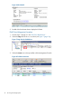
Disk Drive Identification 1. Under the Systems tree in the left panel of HP 3PAR Management Console, select the storage system to be serviced. The Summary tab should be displayed indicating the failed drive (see Figure 4 (page 9)). Figure 4 Summary Tab NOTE: The Physical Disks may indicate Degraded, which indicates that the disk drive is not yet ready for replacement. It may take several hours for the data to be recreated; do not proceed until the status is Failed. 2.
Figure 6 Alert Details 3. Double click the relevant alert to display the full alert. Disk Drive (Magazine) Location 1. 2. Execute steps 1 through 3 in the “Disk Drive Identification ”. Select the Cage link for the Failed drive (see Figure 7 (page 10)). Figure 7 Cage Link for Failed Drive 3. Select the Locate icon in the top toolbar of the Management Console.
4. In the Locate Cage dialog box, enter an appropriate time to allow service personnel to view the LED status of the Drive Enclosure (Cage). See Figure 9 (page 11). NOTE: If necessary, use the Stop Locate icon to halt LED flashing. Figure 9 Locate Cage Dialog Box An icon with a flashing LED will be shown next to the cage, which flashes all drives in this cage except the failed drive. Removing a 2.5 inch Disk 1. 2. 3. 4. Pinch the handle latch to release the handle into open position.
Figure 11 Removing a 3.5 inch disk drive Installing a Disk Drive CAUTION: Blank disk drive carriers are provided and must be used if all slots in the enclosure are not filled with disk drives. CAUTION: To avoid potential damage to equipment and loss of data, handle disk drives carefully. Each disk drive includes a green and amber LED on the front to indicate disk drive status. NOTE: type.
Figure 12 7200 and 7400 Two Node System (HP M6710 Drive Enclosure) Installing a 3.5 inch disk drive (LFF) 1. 2. 3. Press the handle latch to open the handle. Position the disk drive so the handle opens from the left and slide it into the enclosure. Push firmly until the handle fully engages and clicks. Figure 13 Installing a 3.5 inch disk drive Disk Drive Verification 1. 2. Verify that the disk drive has been successfully replaced. Redisplay the physical disks to monitor.
NOTE: Users can select the column header State to resort. NOTE: Until data has been restored, the original disk drive will display as Failed and the replacement disk drive will display as Degraded. 3. The new drive displays in the same position as the failed drive and the State is listed as Normal. NOTE: The drive that was replaced continues to display in the table as Failed until the disk rebuild is complete, which may take several hours.
Figure 15 7400 4-Node - displayed as DCN1 in software output Figure 16 M6710: 2U24 - displayed as DCS2 in software output Figure 17 M6720: 4U24 - displayed as DCS1 in software output Disk Drive Repair 15
Controller Node (Node) Replacement Procedure CAUTION: Customers should replace a controller node only on StoreServ 7200 Storage; other internal components should be serviced by the ASP. CAUTION: Alloy gray-colored latches on components like the node mean that the component is warm-swappable. HP recommends that the node be shutdown (with the power remaining on) before removing this component. Contact your ASP for node diagnosis and shutdown. CAUTION: minutes.
Figure 18 7200 Node Identification The following figure illustrates the 7400 controller node. Figure 19 7400 Node Identification Node Identification and Preparation NOTE: If the failed node is already halted, it is not necessary to shutdown the node because it is not part of the cluster.
1. Under the Systems tree in the left panel, click the storage system to be serviced. In this case, there is only one controller node present, which indicates that the other node is not part of the cluster. If the node UID LED is blue proceed to step 4 to locate the system. If the node UID LED is not blue, escalate to the next level of support. NOTE: If the node's state is Degraded, it will need to be shutdown to be serviced.
3. Shutdown the node to be replaced: a. Log into SPOCC and access Guided Maintenance for this storage system. In the Guided Maintenance window, click Controller Node (see “Service Processor Onsite Customer Care ” (page 5)). To log into SPOCC, go to https://. b. In the Node Rescue Task Information section, select the node to shut down from the Node ID field, then click Shutdown Node. c.
4. Execute a LOCATE against the System in HP 3PAR Management Console: a. Select the Locate icon in the top toolbar of the Management Console. Figure 20 Select Locate on Management Console Toolbar b. Enter an appropriate time to allow service personnel to view the LED status of the System. NOTE: If necessary use the Stop Locate icon to halt LED flashing.
Node Removal 1. Allow 2-3 minutes for the node to halt, then verify the Node Status LED is flashing green and the Node UID LED is blue, indicating the node is halted. CAUTION: The system does not fail if the node is properly halted before removal, but data loss may occur if the replacement procedure is not followed correctly. NOTE: The Node Fault LED may be amber, depending on the nature of the node failure. Figure 22 Verify Node Status LEDs NOTE: Nodes 1 and 3 are rotated in relation to nodes 0 and 2.
4. Grasp each side of the replacement node and gently slide it into the enclosure. Ensure the node is aligned with the grooves in the slot. CAUTION: 5. Ensure that the node is correctly oriented; alternate nodes are rotated 180°. Keep sliding the node in until it halts against the insertion mechanism. CAUTION: Do not proceed until the replacement node has an Ethernet cable connected to the MFG port.
3. Under the Systems tree in the left panel, click the storage system just serviced. NOTE: The storage system status is good and the alerts associated with the failure have been auto-resolved by the system and removed.
1. 2. Unpack the replacement node and place it on an ESD safe mat. Remove the node cover: a. Loosen the two thumbscrews that secure the node cover to the node. b. Lift the node cover and remove. 3. If a PCIe adapter exists in the failed node: a. Unpack the replacement PCIe adapter and place it on a ESD safe mat. b. Remove the PCIe adapter riser card from the replacement node by grasping the blue touch point on the riser card and pulling the riser card up and away from the node. c.
3. 4. 5. 6. 7. At the rear of the rack, remove cables from the failed node. Pull the gray node rod to remove the node from the enclosure. When the node is halfway out of the enclosure, use both hands to slide the node out completely. Set the node on the ESD safe mat next to the replacement node for servicing. Push in the failed node’s grey rod to ready it for packaging and provide differentiation from the replacement node. Node Replacement 1.
Node Verification 1. Verify that the node has been successfully replaced: a. Under the Systems tree in the left panel, double click the storage system just serviced. b. In the lower, right of the Summary tab,in the Health section, check that the State is Normal. NOTE: If the state is not normal contact your ASP for further assistance. Figure 24 Verifying the Node Status 2. Select Controller Nodes.
Typically the State is listed as Loss sync, the Mode as Initiator and the Connected Device Type as Free. 3. Verify that the SFP has been successfully replaced by refreshing the above pane. State should now be listed as Ready, the Mode as Target and the Connected Device Type as Host. To perform maintenance using CLI, access SPMAINT: 1. In the 3PAR Service Processor Menu, select option 7 Interactive CLI for an InServ. 2.
0:3:1 peer 1:0:1 initiator 1:0:2 initiator 1:1:1 target 1:1:2 target 1:2:1 initiator 1:2:2 initiator 1:2:3 initiator 1:2:4 initiator 1:3:1 peer - • offline IP RCIP0 SAS ready 50002ACFF70185A6 50002AC1020185A6 disk SAS ready 2FF70002AC0185A6 21110002AC0185A6 host FC loss_sync 2FF70002AC0185A6 21120002AC0185A6 free FC loss_sync 2FF70002AC0185A6 21210002AC0185A6 free FC loss_sync 2FF70002AC0185A6 21220002AC0185A6 free FC loss_sync 2FF70002AC0185A6 21230002AC0185A6 free FC loss_sync 2FF70002AC01
1:1:1 1:1:2 1:2:1 1:2:2 1:2:3 1:2:4 1:3:1 RCIP1 • target target initiator initiator initiator initiator peer - ready 2FF70002AC0185A6 21110002AC0185A6 host FC - ready 2FF70002AC0185A6 21120002AC0185A6 host FC - loss_sync 2FF70002AC0185A6 21210002AC0185A6 free FC - loss_sync 2FF70002AC0185A6 21220002AC0185A6 free FC - loss_sync 2FF70002AC0185A6 21230002AC0185A6 free FC - loss_sync 2FF70002AC0185A6 21240002AC0185A6 free FC - offline rcip IP - 0002AC8004BD showport -sfp to verify
5. 6. Replace the SFP. See “Replacing an SFP” (page 30). In the HP 3PAR Management Console, verify that the SFP is successfully replaced. The replaced port State is listed as Ready, the Mode is listed as Target, and the Connected Device Type is listed as Host. Figure 27 Port details Replacing an SFP 1. 2. 3. 4. 5. 30 After identifying the SFP that requires replacement, disconnect the cable and lift the retaining clip to carefully slide the SFP out of the slot.
2 Understanding LED Indicator Status Storage system components have LEDs to indicate status of the hardware and whether it is functioning properly. These indicators help diagnose basic hardware problems. You can quickly identify hardware problems by examining the LEDs on all components using the tables and illustrations in this chapter. Enclosure LEDs Bezels LEDs The bezels are located at the front of the system on each side of the drive enclosure and include three LEDs.
Figure 29 Disk Drive LEDs Table 2 Disk drive LEDs LED Appearance Status Indicates 1 - Fault Amber On Disk failed and is ready to be replaced. Flashing The locatecage command has been issued. Fault LEDs for failed disk drives do not blink. The I/O module Fault LEDs at the rear of the enclosure also blink. On Normal operation Flashing Activity 2 - Activity Green Storage System Component LEDs The storage system includes the following components in the enclosure at the rear of the system.
Figure 30 PCM LEDs Table 3 (page 33) describes the LED states.
Figure 31 Drive PCM LEDs Table 4 (page 34) describes the drive PCM LED states.
Figure 33 M6720 I/O Module Table 5 I/O module LEDs LED Icon Function Appearance State Meaning Power Green On Power is on Off Power is off On Fault Off Normal operation Flashing Locate command issued Fault Amber External Port Activity LEDs Function Appearance State Meaning External Port Activity; 4 LEDs for Data Ports 0 through 3 Green On Ready, no activity Off Not ready or no power Flashing Activity Controller Node and Internal Component LEDs Controller node LEDs are shown
Ethernet LEDs The controller node has two built-in Ethernet ports and each includes two LEDs (see Table 7 (page 36)). Table 7 Ethernet LEDs Left Link Up Speed Right Activity Green On 1 Gbe Link Amber On 100 Mbit Link Off No link established or 10 Mbit Link On No link activity Off No link established Flashing Link activity Green Node FC and CNA Port LEDs The controller node has two FC ports; each includes two LEDs. The arrow head-shaped LEDs point to the port they are associated with.
Node FC and CNA Port Numbering Port position is displayed as Node:Slot:Port (N:S:P) in the Management Console. Table 11 FC Ports Slot:Port FC-1 1:1 FC-2 1:2 Table 12 FC Adapter Ports Slot:Port 1 2:1 2 2:2 3 2:3 4 2:4 Table 13 CNA Ports Slot:Port 1 2:1 2 2:2 SAS Port LEDs The controller node has two SAS ports and each includes four LEDs, numbered 0–3: Figure 34 SAS port LEDs Table 14 SAS port LEDs Appearance Green Indicates Off No activity on port.
Interconnect Port LEDs The controller node has two interconnect ports and each includes two LEDs. NOTE: Incorrectly configured interconnect cables illuminate amber port LEDs. Table 15 Interconnect port LEDs 7200 A 7200 does not use any external interconnect links. Interconnect port LEDs should always be off. 7400 Fault Amber On Failed to establish link connection Off No error currently on link Flashing 1. Interconnect cabling error 2. Controller node in wrong slot 3.
3 Support and Other Resources Contacting HP For worldwide technical support information, see the HP support website: http://www.hp.
For information about: See: Migrating data from one HP 3PAR storage system to another HP 3PAR-to-3PAR Storage Peer Motion Guide 40 Configuring the Secure Service Custodian server in order to monitor and control HP 3PAR storage systems HP 3PAR Secure Service Custodian Configuration Utility Reference Using the CLI to configure and manage HP 3PAR Remote Copy HP 3PAR Remote Copy Software User’s Guide Updating HP 3PAR operating systems HP 3PAR Upgrade Pre-Planning Guide Identifying storage system compo
For information about: See: Planning for HP 3PAR storage system setup Hardware specifications, installation considerations, power requirements, networking options, and cabling information for HP 3PAR storage systems HP 3PAR 7200 and 7400 storage systems HP 3PAR StoreServ 7000 Storage Site Planning Manual HP 3PAR 10000 storage systems HP 3PAR StoreServ 10000 Storage Physical Planning Manual HP 3PAR StoreServ 10000 Storage Third-Party Rack Physical Planning Manual Installing and maintaining HP 3PAR 7200
Typographic conventions Table 16 Document conventions Convention Element Bold text • Keys that you press • Text you typed into a GUI element, such as a text box • GUI elements that you click or select, such as menu items, buttons, and so on Monospace text • File and directory names • System output • Code • Commands, their arguments, and argument values • Code variables • Command variables Bold monospace text • Commands you enter into a command line interface • Syste
4 Documentation feedback HP is committed to providing documentation that meets your needs. To help us improve the documentation, send any errors, suggestions, or comments to Documentation Feedback (docsfeedback@hp.com). Include the document title and part number, version number, or the URL when submitting your feedback.
A Installing Storage Software Manually WARNING! Use this procedure only if access to HP SmartStart CD or the Storage System and Service Processor Setup wizards are not available. This appendix describes how to manually set up and configure the storage system software and SP. You must execute these scripted procedures from a laptop after powering on the storage system. Connecting to the Laptop You can connect the laptop directly to a controller node or SP using the connector cables.
Figure 35 Maintenance PC Connector Pin-outs Service Processor Connector Pin-outs Use at the SP end of a standard Ethernet cable and in conjunction with the laptop adapter (PN 180-0055-01) to allow serial connection to the SP.
7. Set up the system to wipe and rerun ootb 8. Cancel a wipe 9. Perform a deinstallation 10. Update the system for recently added hardware (admithw) 11. Check system health (checkhealth) 12. Exit > 1 WARNING! Proceeding with the system setup script causes complete and irrecoverable loss of data. Do not perform this procedure on a system that has already undergone the system setup.
NOTE: The system name can include only letters, numbers and the special characters “.-_”, (dot, hyphen, underscore) and can be no more than 31 characters long. The first character in the sequence must be a letter or number. Enter the InServ system name ==> Cluster will be initialized with the name IS THIS THE CORRECT NAME? yes/change => yes Cluster is being initialized with the name ...Please Wait... 8. Verify the OS version is correct.
14. Verify the correct license is displayed and press Enter. If the license information is not correct, type c and press Enter to continue with the system setup. After completing the system setup, contact your local service provider for technical support to obtain the proper license keys. 15. Complete the network configuration: a. When prompted, type the number of IP addresses used by the system (usually 1) and press Enter. b. Type the IP address and press Enter. c. Type the netmask and press Enter.
4. When prompted to update the SP, verify that the software version is correct. Type y and press Enter to continue with the update process. Mounting CDROM... Using spinstaller from /sp/sw/sp/2.5.1.GA-15/ tpdSPInFormOS3.1.2.226-3.1.2.226-12.i386.rpm Do You wish to update the SP from /mnt/cdrom? (y or n) y 5. When the installation process completes, the SPMaint main menu reappears. To verify the current software versions after installation, type 1 for SP Control/Status.
To add the storage system to the SP: 1. Connect the maintenance PC to the SP. 2. In the SPMaint, type 3 and press Enter to select InServ Configuration Management.
Username: Password: NOTE: If adding a storage system fails, exit from the process and check the SP software version for compatibility. Update the SP with the proper InForm OS version before adding additional systems. 6. After successfully adding the system, press Enter to return to the SP menu. ... validating communication with ... site key ok interrogating for version number... Version 3.1.x.GA-x reported on
where is the host persona ID number, is the name of the test host, and is the WWN of an HBA in the host machine. This HBA must be physically connected to the storage system. 3. After you have defined a system host for each physically connected WWN, verify host configuration information for the storage system as follows: 192.168.46.249 cli% showhost 4. Use the controlport command to set each target port as follows: 192.168.46.
B Node Rescue Service Processor (Physical) Node Rescue The SP node rescue should be used only in cases when the storage system includes a physical SP and no nodes remain in the cluster or when all nodes are down. NOTE: For SP node rescue, you can specify whether to use the public Ethernet port (MGMT) or the private Ethernet port and a crossover cable. To perform an SP node rescue: 1. Connect the crossover cable to the SP and to the MGMT port of the node that is being rescued. 2.
5. 6. 7. After the node has booted, verify that the node status LED is blinking green in unison with the other node LEDs, indicating that the node has joined the cluster, then press Enter to continue. Select the following: • 1 Deconfigure Node Rescue • x to return to return to the main menu • 7 Interactive CLI for an InServ, then select the desired system Issue the following commands: • shownode to verify that all nodes have joined the cluster.
C Illustrated Parts Catalog The following shows each component of the storage system for all replaceable hardware parts including the part number, full description, quantity, and CSR type.
Figure 39 2.5-inch SFF disk drive Figure 40 3.5-inch LFF disk drive Table 17 Drive Chassis FRUs Material Number Description Qty Per Chassis CSR Type 683232-001 SPS-Enclosure Midplane 2U24 Assy 1 Not 683233-001 SPS-Enclosure Midplane 4U24 Assy 1 Not 683234-001 SPS-Drive Carrier SFF SSD Assy 683235-001 SPS-Drive Carrier LFF HDD Assy 683236-001 SPS-Drive Carrier LFF SSD Assy 24–480 Mandatory The following are CSR-A parts: 56 697387-001 SPS-Drive HD 300GB 6G SAS 15K M6710 2.
Table 17 Drive Chassis FRUs (continued) Material Number Description Qty Per Chassis CSR Type 697389-001 SPS-Drive HD 900GB 6G SAS 10K M6710 2.5in HDD Mandatory 697390-001 SPS-Drive HD 2TB 6G SAS 7.2K NL M6720 3.5in HDD Mandatory 697391-001 SPS-Drive HD 3TB 6G SAS 7.2K NL M6720 3.5in HDD Mandatory 697392-001 SPS-Drive 200GB 6G SAS SLC M6710 2.5in SSD Mandatory 703521–001 SPS-Drive HD 100GB 6G SAS 3.5in HDD Mandatory 703522–001 SPS-Drive 100GB 6G SAS 3.
Figure 42 764W Power Cooling Module Battery Figure 43 580W Power Cooling Module Figure 44 I/O Module 58 Illustrated Parts Catalog
Table 18 Storage System Components Part Number Description Qty.
Figure 47 4-port Fibre Channel Adapter Figure 48 2-port CNA Adapter Figure 49 FC SFP Adapter 60 Illustrated Parts Catalog
Table 19 Controller Node and Components Part Number Description Qty.
Table 20 Internal Node Components Callout Part Number Description Qty.
Table 21 Storage System Cables (continued) Part Number Description Qty. CSR Type 649994-001 SPS-Cable FC LC-LC OM3 100 M Not 659061-001 SPS-Cable FC LC-LC OM3 6 M Not 408765-001 PS-CA,EXT MINI SAS, 0.5M 408767-001 SPS-CA,EXT MINI SAS, 2M Mandatory 408769-001 SPS-CA,EXT MINI SAS, 6M Mandatory 456096–001 SPSSFP+, 10G BLc, SR Optional Table 22 Miscellaneous Parts Part Number Description Qty.
Table 23 Service Processor Parts (continued) 64 Part Number Description 5183–5691 Ethernet Cable 50 ft. CAT5 RJ45 M/M C7542A HP Ethernet 15.2m (50 ft) CAT5e RJ45 M/M Cable Illustrated Parts Catalog Qty.
D Deinstallation Use these procedures when removing systems from an operating site and relocating to an alternate site. Before uninstalling a storage system: • Obtain drive enclosure shipping containers, one per enclosure. • Verify with a System Administrator that the system is prepared for shutdown. • Complete the storage system inventory after uninstalling the system.