HP 3PAR StoreServ 7000 Storage Troubleshooting Guide This guide is intended for experienced users and system administrators troubleshooting HP 3PAR StoreServ 7000 Storage systems and have a firm understanding of RAID schemes.
© Copyright 2014 Hewlett-Packard Development Company, L.P. Confidential computer software. Valid license from HP required for possession, use or copying. Consistent with FAR 12.211 and 12.212, Commercial Computer Software, Computer Software Documentation, and Technical Data for Commercial Items are licensed to the U.S. Government under vendor's standard commercial license. The information contained herein is subject to change without notice.
Contents 1 Identifying Storage System Components........................................................6 Understanding Component Numbering.......................................................................................6 Drive Enclosures...................................................................................................................6 Controller Nodes.................................................................................................................
Cage Example 5...........................................................................................................33 Cage Suggested Action 5..............................................................................................33 Data Encryption (DAR)........................................................................................................34 Format of Possible DAR Exception Messages.....................................................................35 DAR Suggested Action.......
Format of Possible Port Exception Messages......................................................................47 Port Suggested Actions...................................................................................................47 Port Example 1.............................................................................................................47 Port Suggested Action 1.................................................................................................47 Port Example 2..........
1 Identifying Storage System Components NOTE: The illustrations in this chapter are used examples only and may not reflect your storage system configuration. Understanding Component Numbering Due to the large number of possible configurations, component placement and internal cabling is standardized to simplify installation and maintenance. System components are placed in the rack according to the principles outlined in this chapter, and are numbered according to their order and location in the cabinet.
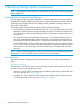
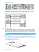
Figure 1 HP M6710 Drive Enclosure (2U24) Figure 2 HP M6720 Drive Enclosure (4U24) Controller Nodes The controller node caches and manages data in a system providing a comprehensive, virtualized view of the system. The controller nodes are located at the rear of the node enclosure. The HP 3PAR StoreServ 7200 Storage system contains two nodes numbered 0 and 1 (see Figure 3 (page 7)). The HP 3PAR StoreServ 7400 Storage system has either two nodes or four nodes.
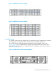
Figure 4 HP 3PAR StoreServ Four-node Configuration Storage Numbering PCIe Slots and Ports This table describes the default port configurations for the HP 3PAR StoreServ 7000 Storage systems. See Table 1 (page 8) for details.
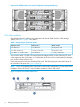
Table 2 Description of Controller Node Ports Item Port 1 2 Ethernet MGMT--Connects to the storage array management interfaces RC--Connects to Remote Copy 2 Fibre Channel (FC-1 and FC-2)--Connects to host systems 3 SAS (DP-2 and DP-1)--Connects the drive enclosures and I/O modules using SAS cables 4 Node Interconnect--Connects four directional interconnect cables that connect the controller nodes (four node 7400 only) 5 PCIe slot for optional four-port 8 Gb/s FC HBA or two-port 10 Gb/s CNA NOTE:
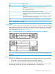
Figure 7 PCM Numbering In the HP M6720 Drive Enclosure, the two PCMs are located diagonally from one another. The remaining PCM slots are blank. See Figure 8 (page 10)). Figure 8 PCMs in a HP M6710 (2U) and HP M6720 (4U) Drive Enclosures Power Distribution Units Two power distribution units (PDU) are mounted horizontally at the bottom of the rack. The PDUs are numbered 0 and 1 from bottom to top.
2 Understanding LED Indicator Status Storage system components have LEDs indicating status of the hardware. Use the LED indicators to help diagnose basic hardware problems. This chapter provides tables and illustrations of component LEDs. Enclosure LEDs Bezel LEDs The bezel LEDs are located at the front of the system on each side of the drive enclosure. The bezels have three LED indicators. See Figure 10 (page 11).
Disk Drive LEDs Disk Drive LEDs are located on the front of the disk drives. Disk drives have two LED indicators. Figure 11 Location of Disk Drive LEDs Table 4 Description of Disk Drive LEDs Callout LED LED Appearance Indicates 1 Activity Green On – Normal operation Flashing – Activity 2 Fault Amber On – Disk failed and is ready to be replaced.
Figure 12 Location of Controller Node PCM LEDs Table 5 Description of Controller Node PCM LEDs Icon Description AC input fail PCM OK Fan Fail DC Output Fail Battery Fail Appearance Indicates On No AC power or PCM fault Flashing Firmware download On AC present and PCM On / OK Flashing Standby mode On PCM fail or PCM fault Flashing Firmware download On No AC power, PCM fault or out of tolerance Flashing Firmware download On Hard fault (not recoverable) Flashing Soft fault (recover
Table 5 Description of Controller Node PCM LEDs (continued) Icon Description Battery Good Appearance Indicates On Present and charged Flashing Charging or disarmed Green Drive PCM LEDs The following figure shows the location of drive 580 W PCM LEDs. See Table 6 (page 14) for details of PCM LEDs..
Table 6 Description of Drive PCM LEDs (continued) Icon Description DC Output Fail LED Appearance Indicates On No AC power, PCM fault or out of tolerance Flashing Firmware download Amber I/O Module LEDs I/O modules are located on the back of the system. I/O modules have two mini-SAS universal ports, which can be connected to HBAs or other ports. Each port includes External Port Activity LEDs, labeled 0 to 3. The I/O module also includes a Power and Fault LED.
Table 7 Description of I/O module Power and Fault LEDs (continued) Icon Function Appearance State Indicates Fault Amber On Fault Off Normal operation Flashing Locate command issued External Port Activity LEDs Figure 16 Location of External Port Activity LEDs 16 Function Appearance State Indicates External Port Activity; 4 LEDs for Data Ports 0 through 3 Green On Ready, no activity Off Not ready or no power Flashing Activity Understanding LED Indicator Status
Controller Node and Internal Component LEDs NOTE: Enter the locatenode command to flash the hotplug LED blue.
Figure 18 Location of Ethernet LEDs Table 9 Description of Ethernet LEDs Callout LED Appearance Indicates 1 Link Up Speed Green On – 1 GbE Link Amber On – 100 Mb Link Off – No link established or 10 Mb Link 2 Activity Green On – No Link activity Off – No link established Flashing – Link activity FC Port LEDs The controller node has two FC ports. Each FC port has two LEDs. The arrow-head shaped LEDs point to the associated port.
SAS Port LEDs The controller node has two SAS ports. Each SAS port has four LEDs and numbered 0 to 3: Figure 20 Location of SAS Port LEDs Table 11 Description of SAS port LEDs Callout LED Appearance Indicates 1 DP-1 Green Off– SAS link is present or not, this LED does not remain lit Flashing–Activity on port 2 DP-2 Green Off–SAS link is present or not, this LED does not remain lit Flashing–Activity on port Interconnect Port LEDs The controller node has two interconnect ports.
Table 12 Description of Interconnect Port LEDs (continued) Off – Link not yet established 2 Fault Amber On – Failed to establish link connection Off – No errors currently on link Flashing – Cluster link cabling error, controller node in wrong slot, or serial number mismatch between controller nodes.
Table 14 Description of CNA Port LEDs Callout LED Appearance Indicates 1 Link Green Off – Link down On – Link up 2 ACT (Activity) Green Off – No activity On – Activity Service Processor LEDs The HP 3PAR SP (Proliant DL320e) LEDs are located at the front and rear of the SP.
Figure 25 Rear Panel LEDs Table 16 Rear panel LEDs Item LED Appearance Description 1 NIC link Green Link Off No link Green or Flashing Green Activity Off No activity Blue Active Flashing Blue System is being managed remotely Off Deactivated Green Normal 2 3 4 NIC status UID LED/button Power supply NOTE: May not be applicable to Off your system (for hot-plug HP CS power supplies ONLY) Off = one or more of the following conditions: • Power is unavailable • Power supply has failed
3 Powering Off/On the Storage System This chapter describes how to power the storage system on and off. Powering Off the Storage System NOTE: Power distribution units (PDU) in any expansion cabinets connected to the storage system may need to be shut off. Use the locatesys command to identify all connected cabinets before shutting down the system. The command blinks all node and drive enclosure LEDs.
NOTE: To avoid any cabling errors, all drive enclosures must have at least one or more hard drive(s) installed before powering on the enclosure. 4. 5. 24 Power on the node enclosure PCMs. Verify the status of the LEDs. See “Understanding LED Indicator Status” (page 11).
4 Alerts Alerts are triggered by events that require system administrator intervention. This chapter provides a list of alerts identified by message code, the messages, and what action should be taken for each alert. To learn more about alerts, see the HP 3PAR StoreServ Storage Concepts Guide. For information about system alerts, go to HP Guided Troubleshooting at http://www.hp.com/ support/hpgt/3par and select your server platform. To view the alerts, use the showalert command.
8. 26 Alerts On the suggested actions page, scroll through the list to find the message state listed in the alert message. The recommended action is listed next to the message state.
5 Troubleshooting The HP 3PAR OS CLI checkhealth command checks and displays the status of storage system hardware and software components. For example, the checkhealth command can check for unresolved system alerts, display issues with hardware components, or display information about virtual volumes that are not optimal. By default the checkhealth command checks most storage system components, but you can also check the status of specific components.
The following information is reported with the -detail option: Component ----Identifier---- -----------Description------Alert sw_port:1:3:1 Port 1:3:1 Degraded (Target Mode Port Went Offline) Alert sw_port:0:3:1 Port 0:3:1 Degraded (Target Mode Port Went Offline) Alert sw_sysmgr Total available FC raw space has reached threshold of 800G (2G remaining out of 544G total) Alert sw_sysmgr Total FC raw space usage at 307G (above 50% of total 544G) Date -Date is not the same on all nodes LD LD vlun vlun vlun vlun
Table 18 Component Functions (continued) Component Function Node Displays node conditions that are not optimal PD Displays PDs with states or conditions that are not optimal Port Displays port connection issues RC Displays Remote Copy issues SNMP Displays issues with SNMP Task Displays failed tasks VLUN Displays inactive VLUNs and VLUNs that have not been reported by the host agent VV Displays VVs that are not optimal Alert Displays unresolved alerts and shows any alerts generated by showa
Cage Cage Cage Cage Cage cage: cage: cage: cage: cage: "Power supply fan is " "Power supply is " (Degraded, Failed, Not_Present) "Power supply AC state is " "Cage is in 'servicing' mode (Hot-Plug LED may be illuminated)" "Firmware is not current" Cage Example 1 Component -------------Description-------------- Qty Cage Cages missing A loop 1 Cage SFPs with low receiver power 1 Component -Identifier- --------Description--------
0:2 2000001862953303 Green 0:3 2000001862953888 Green 35 0xdc Loop fail 0xdc 31 0xda Loop fail 0xda OK OK cli% showcage -sfp cage4 Cage FCAL SFP -State- --Manufacturer-- MaxSpeed(Gbps) TXDisable TXFault RXLoss DDM 4 0 0 OK FINISAR CORP. 4.1 No No Yes Yes 4 1 1 OK FINISAR CORP. 4.
VendorId,ProductId 3PARdata,DC2 Unique_ID 10320300000AD000 Power Supply Info State Fan State AC Model ps0 Failed OK Failed POI
Cage Example 4 SComponent ---------Description--------- Qty Cage Cages not on current firmware 1 Component -Identifier- ------Description-----Cage cage:3 Firmware is not current Cage Suggested Action 4 Check the drive cage firmware revision using the commands showcage and showcage -d cageX. The showfirwaredb command displays current firmware level required for the specific drive cage type. NOTE: The DC1 and DC3 cages have firmware in the FCAL modules.
-----------Cage detail info for cage4 --------Fibre Channel Info PortA0 PortB0 PortA1 PortB1 Link_Speed 2Gbps --- 4Gbps ----------------------------------SFP Info----------------------------------FCAL SFP -State- --Manufacturer-- MaxSpeed(Gbps) TXDisable TXFault RXLoss DDM 0 0 OK SIGMA-LINKS 2.1 No No No Yes 1 1 OK FINISAR CORP. 4.
Format of Possible DAR Exception Messages Dar -- "There are 5 disks that are not self-encrypting" DAR Suggested Action Remove the drives that are not self-encrypting from the system because the non-encrypted drives cannot be admitted into a system that is running with data encryption. Also, if the system is not yet enabled for data encryption, the presence of these disks prevents data encryption from being enabled.
LD Checks the following and displays logical disks (LD) that are not optimal: • Preserved LDs • Verifies that current and created availability are the same • Owner and backup • Verifies preserved data space (pdsld) is the same as total data cache • Size and number of logging LDs Format of Possible LD Exception Messages LD LD LD LD ld: ld: ld: ld: "LD "LD "LD "LD is not mapped to a volume" is in write-through mode" has preserved RAID sets and preserved chu
LD Example 2 Component -------Description-------- Qty LD LDs in write through mode 3 Component -Identifier-- --------Description--------LD ld:Ten.usr.12 LD is in write-through mode LD Suggested Action 2 Examine the identified LDs for failed or missing disks by using the following CLI commands:showld, showld –d, showldch, and showpd. Write-through mode (WThru) indicates that host I/O operations must be written through to the disk before the host I/O command is acknowledged.
Id Name CPG RAID Own SizeMB RSizeMB RowSz StepKB SetSz Refcnt Avail CAvail 32 R1.usr.0 --1 0/1/3/2 256 512 1 256 2 0 cage ch cli% showldch R1.usr.
Network Displays Ethernet issues for administrative and Remote Copy over IP (RCIP) networks that have been logged on the previous 24-hours. Also, reports the storage system has fewer than two nodes with working administrative Ethernet connections. • Check the number of collisions in the previous day log. The number of collisions should be less than 5% of the total packets for the day. • Check for Ethernet errors and transmit (TX) or receive (RX) errors in previous day’s log.
Admin interface on node 0 MAC Address: 00:02:AC:25:04:03 RX Packets: 1225109 RX Bytes: 1089073679 RX Errors: 0 RX Dropped: 0 RX FIFO Errors: 0 RX Frame Errors: 60 RX Multicast: 0 RX Compressed: 0 TX TX TX TX TX TX TX TX Packets: Bytes: Errors: Dropped: FIFO Errors: Collisions: Carrier Errors: Compressed: 550205 568149943 0 0 0 0 0 0 Node Checks the following node conditions and displays nodes that are not optimal: • Verifies node batteries have been tested in the last 30 days • Offline nodes • Powe
NOTE: In the example below, the battery state is considered degraded because the power supply is failed.
Node Example 3 Component -Identifier- --------------Description---------------Node node:3 Node:3, Power Supply:1, Battery:0 has not been tested within the last 30 days Node Suggested Action 3 The indicated battery has not been tested in 30 days. A node backup battery is tested every 14 days under normal conditions. If the main battery is missing, expired, or failed, the backup battery is not tested.
PD disk: "Disk is experiencing a high level of I/O per second: " PD -- There is at least one active servicemag operation in progress The following checks are performed when the -svc option is used, or on 7400/7200 hardware: PD File: "Folder not found on all Nodes in " PD File: "Folder not found on some Nodes in " PD File: "File not found on all Nodes in " PD File: "File not found on some Nodes in " PD Disk: "
1 1 OK SIGMA-LINKS 2.
3 cage3 2:0:4 0 --- 0 32 29-41 2.37 2.37 DC2 n/a -----------Cage detail info for cage3 --------Fibre Channel Info PortA0 PortB0 PortA1 PortB1 Link_Speed 2Gbps --- 0Gbps ----------------------------------SFP Info----------------------------------FCAL SFP -State- --Manufacturer-- MaxSpeed(Gbps) TXDisable TXFault RXLoss DDM 0 0 OK SIGMA-LINKS 2.1 No No No Yes 1 1 OK SIGMA-LINKS 2.
PD Example 4 Component --Identifier-- -------Description---------PD disk:3 Detailed State: old_firmware PD Suggested Action 4 The identified disk does not have firmware that the storage system considers current. When a disk is replaced, the servicemag operation should upgrade the disk's firmware. When disks are installed or added to a system, the admithw command can perform the firmware upgrade. Check the state of the disk by using CLI commands such as showpd -s, showpd -i, and showfirmwaredb.
PD Suggested Action 6 Check the release notes for mandatory updates and patches. Install updates and patches to HP 3PAR OS as needed to support the PD in the cage.
In the following example an RX power level of 361 microwatts (uW) for Port 0:0:1 DDM is a good reading; and 98 uW for Port 0:0:2 is a weak reading (< 100 uW). Normal RX power level readings are 200-400 uW.
0:3:1 0:3:2 OK FINISAR_CORP. - 2.1 No No No Yes Port Example 3 Component -Description- Qty Port Disabled SFPs 1 Component -Identifier- --Description-Port port:3:5:1 SFP is disabled Port Suggested Action 3 A node-port SFP will be disabled if the port has been placed offline using the controlport offline command. See Example 4. cli% showport N:S:P -State3:5:1 OK 3:5:2 OK -sfp -Manufacturer- MaxSpeed(Gbps) TXDisable TXFault RXLoss DDM FINISAR_CORP. 4.1 Yes No No Yes FINISAR_CORP. 4.
Port Suggested Action 5 The output indicates that the port's mode, such as an initiator or target, is not correct for the connection type, such as disk, host, iSCSI or RCFC. Useful CLI command include: showport, showport -c, showport -par, showport -rcfc, showcage.
SNMP Displays issues with SNMP. Attempts the showsnmpmgr command and reports errors if the CLI returns an error. Format of Possible SNMP Exception Messages SNMP -- SNMP Example Component -Identifier- ----------Description--------------SNMP -Could not obtain snmp agent handle. Could be misconfigured. SNMP Suggested Action Any error message that can be produced by showsnmpmgr can display. Task Displays failed tasks. Checks for any tasks that have failed within the past 24 hours.
Detailed status is as follows: 2010-10-22 10:35:36 PDT Created 2010-10-22 10:35:36 PDT Updated 2010-10-22 10:35:36 PDT Errored task. Executing "upgradecage -a -f" as 0:12109 upgradecage: Invalid option: -f VLUN Displays host agent inactive and non-reported virtual LUNs (VLUNs). Also reports VLUNs that have been configured but are not currently being exported to hosts or host-ports.
Format of Possible VV Exception Messages VV VV VV VV VV VV vv: "IO to this volume will fail due to no_stale_ss policy" vv: "Volume has reached snapshot space allocation limit" vv: "Volume has reached user space allocation limit" vv: "VV has expired" vv: "Detailed State: " (failed or degraded) cpg: "CPG is unable to grow SA (or SD) space" VV Suggested Action Check status by using CLI commands such as showvv, showvv -d, and showvv -cpg.
This message displays either in a dialog box or inline. If the message displays in a dialog box, you can click Retry or Cancel in the wizard. If the message appears inline, you can only click Next in the wizard. • Setup encountered an unknown error ({0}). Contact HP support for help. This message displays in a dialog box with Retry and Cancel buttons, where {0} is the error number. For information about contacting HP Support, see “Contacting HP Support about System Setup” (page 60).
{0} will be the version of the TPD package that the user must install so that the SP will work with the storage system. • The SP does not have an HP 3PAR OS version installed. Use SPOCC to install an HP 3PAR OS package. This message displays as an inline error on the bottom of the wizard page when no TPD package is installed. The SP needs a TPD package installed in order to communicate with an HP 3PAR StoreServ Storage system.
• The storage system found an error while checking cabling health. Details are listed below. This error message displays in a dialog box with Retry and Cancel buttons. The message is followed by a list of errors. The errors may include: ◦ Cage {0} is connected to the same node twice through ports {1} and {2}. Re-cable this cage. This error displays if a cage is connected to the same node twice. {0} will be the name of the cage and {1} and {2} will be the port locations where the cage is connected.
{0} did not come back after the firmware upgrade. Contact HP support for help. This error message displays in a dialog box with Retry and Cancel buttons. This error might occur after the drive cages have had a firmware upgrade. {0} will be the name of the cage with the problem. Contact HP Support. For information about contacting HP Support, see “Contacting HP Support about System Setup” (page 60). • The storage system found an error while checking disk health. Details are listed below.
• Unable to set the storage system network configuration. An invalid IPv4 gateway was specified. This message displays in a dialog box. The error occurs if the storage system detects that the defined IPv4 gateway address is invalid. Click Back and specify a valid IPv4 gateway address. • Unable to set the storage system network configuration. The specified IPv4 gateway address is not reachable by using the specified storage system IPv4 address. This message displays in a dialog box.
Click Cancel to close the wizard, and then begin the setup process again. • Unable to set the storage system NTP server. The storage system's admin volume has not been created. This must be created before any networking information is created. Contact HP support for help. This error message displays in a dialog box with Retry and Cancel buttons. This error occurs if a previous command failed and the wizard did not detect the error, or if the system was rebooted for any reason during installation.
5. 6. In the Action column, click Download for each log file: SPSETLOG.log Service Processor setup log ARSETLOG.system_serial_number.log Storage System setup log errorLog.log General errors Zip the downloaded log files. Contacting HP Support about System Setup For worldwide technical support information, see the HP support website: http://www.hp.
6 Support and Other Resources Contacting HP For worldwide technical support information, see the HP support website: http://www.hp.
For information about: See: Migrating data from one HP 3PAR storage system to another HP 3PAR-to-3PAR Storage Peer Motion Guide 62 Configuring the Secure Service Custodian server in order to monitor and control HP 3PAR storage systems HP 3PAR Secure Service Custodian Configuration Utility Reference Using the CLI to configure and manage HP 3PAR Remote Copy HP 3PAR Remote Copy Software User’s Guide Updating HP 3PAR operating systems HP 3PAR Upgrade Pre-Planning Guide Identifying storage system compo
For information about: See: Planning for HP 3PAR storage system setup Hardware specifications, installation considerations, power requirements, networking options, and cabling information for HP 3PAR storage systems HP 3PAR 7200, 7400, and 7450 storage systems HP 3PAR StoreServ 7000 Storage Site Planning Manual HP 3PAR StoreServ 7450 Storage Site Planning Manual HP 3PAR 10000 storage systems HP 3PAR StoreServ 10000 Storage Physical Planning Manual HP 3PAR StoreServ 10000 Storage Third-Party Rack Physic
Typographic conventions Table 19 Document conventions Convention Element Bold text • Keys that you press • Text you typed into a GUI element, such as a text box • GUI elements that you click or select, such as menu items, buttons, and so on Monospace text • File and directory names • System output • Code • Commands, their arguments, and argument values • Code variables • Command variables Bold monospace text • Commands you enter into a command line interface • Syste
7 Documentation feedback HP is committed to providing documentation that meets your needs. To help us improve the documentation, send any errors, suggestions, or comments to Documentation Feedback (docsfeedback@hp.com). Include the document title and part number, version number, or the URL when submitting your feedback.