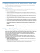
HP 3PAR StoreServ 7000/7450 Storage Cabling Configuration Guide F: 4 Node Systems with Mixed-Size Drive Enclosures Abstract This guide provides cabling information for authorized technicians performing installation and maintenance services on the HP 3PAR StoreServ 7000/7450 Storage systems.
© Copyright 2013 Hewlett-Packard Development Company, L.P. The information contained herein is subject to change without notice. The only warranties for HP products and services are set forth in the express warranty statements accompanying such products and services. Nothing herein should be construed as constituting an additional warranty. HP shall not be liable for technical or editorial errors or omissions contained herein. Acknowledgments Microsoft®, Windows®, are U.S.
Contents 1 Cabling Preparation for HP 3PAR StoreServ 7000/7450.................................8 Following Precautions................................................................................................................8 Identifying and Labeling the Components....................................................................................8 2 Cabling HP 3PAR StoreServ 7000/7450.....................................................11 4 Node 4 Drive Enclosures (2S+2L)............................
4 4 4 4 4 4 4 4 Attach DP-2 Chains to Enclosures.......................................................................................105 Attach DP-2 Chains to Enclosures Between Racks..................................................................106 Review Completed Cabling...............................................................................................107 Review Completed Cabling Between Racks.........................................................................
4 4 4 4 4 4 4 Review Completed Cabling...............................................................................................118 4 Node Interconnect Cabling............................................................................................119 Node 14 Drive Enclosures (12S+2L)......................................................................................115 Attach DP-1 Chains to Enclosures........................................................................................
4 Node 16 Drive Enclosures (14S+2L)......................................................................................168 Attach DP-1 Chains to Enclosures........................................................................................169 Attach DP-2 Chains to Enclosures.......................................................................................170 Review Completed Cabling...............................................................................................
Attach DP-1 Chains to Enclosures Between Racks..................................................................231 Attach DP-2 Chains to Enclosures.......................................................................................232 Attach DP-2 Chains to Enclosures Between Rack...................................................................233 Review Completed Cabling...............................................................................................
1 Cabling Preparation for HP 3PAR StoreServ 7000/7450 The following instructions list important precautions and information about cabling installation options for the HP 3PAR StoreServ Storage system.
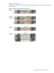
Types of Components Use the red and green color coding to assist with the cabling. Only connect to components sharing the same color.
Labeling the Enclosures Before connecting the cables: • Labels (A, B, C, and D) are provided to help identify the enclosures in the storage system. Apply the labels to each enclosure in a visible location and avoid covering other labels • Apply label A to the controller enclosure with nodes 0 and 1. Alternate the labeling (A/B) on each enclosure below the controller enclosure If applicable, a system using four nodes, apply label C to the controller enclosure with nodes 2 and 3.
2 Cabling HP 3PAR StoreServ 7000/7450 The following illustrative sections provide a rear view of the rack with recommended racking configuration of the system. 4 Node 4 Drive Enclosures (2S+2L) Before you begin cabling the storage system, carefully read or print the following section, including figures 1 and 2, “Identifying and Labeling the Components” (page 8).
Attach DP-1 Chains to Enclosures Red routing 1. 2. 3. 4. Connect Connect Connect Connect Node 0 (DP-1) to the I/O 0 (DP-1) on the A drive enclosure closest to the controller. all A drive enclosures from (DP-2) to (DP-1) working away from the controller. Node 2 (DP-1) to the I/O 0 (DP-1) on the C drive enclosure closest to the controller. all C drive enclosures from (DP-2) to (DP-1) working away from the controller. Green routing 1. 2. 3. 4.
Attach DP-2 Chains to Enclosures Red routing 1. 2. 3. 4. Connect Connect Connect Connect Node 0 (DP-2) to the I/O 0 (DP-1) on the B drive enclosure closest to the controller. all B drive enclosures from (DP-2) to (DP-1) working away from the controller. Node 2 (DP-2) to the I/O 0 (DP-1) on the D drive enclosure closest to the controller. all D drive enclosures from (DP-2) to (DP-1) working away from the controller. Green routing 1. 2. 3. 4.
Review Completed Cabling 14 Cabling HP 3PAR StoreServ 7000/7450
4 Node 6 Drive Enclosures (2S+4L) Before you begin cabling the storage system, carefully read or print the following section, including figures 1 and 2, “Identifying and Labeling the Components” (page 8).
Attach DP-1 Chains to Enclosures Red routing 1. 2. 3. 4. Connect Connect Connect Connect Node 0 (DP-1) to the I/O 0 (DP-1) on the A drive enclosure closest to the controller. all A drive enclosures from (DP-2) to (DP-1) working away from the controller. Node 2 (DP-1) to the I/O 0 (DP-1) on the C drive enclosure closest to the controller. all C drive enclosures from (DP-2) to (DP-1) working away from the controller. Green routing 1. 2. 3. 4.
Attach DP-2 Chains to Enclosures Red routing 1. 2. 3. 4. Connect Connect Connect Connect Node 0 (DP-2) to the I/O 0 (DP-1) on the B drive enclosure closest to the controller. all B drive enclosures from (DP-2) to (DP-1) working away from the controller. Node 2 (DP-2) to the I/O 0 (DP-1) on the D drive enclosure closest to the controller. all D drive enclosures from (DP-2) to (DP-1) working away from the controller. Green routing 1. 2. 3. 4.
Review Completed Cabling 18 Cabling HP 3PAR StoreServ 7000/7450
4 Node 6 Drive Enclosures (4S+2L) Before you begin cabling the storage system, carefully read or print the following section, including figures 1 and 2, “Identifying and Labeling the Components” (page 8).
Attach DP-1 Chains to Enclosures Red routing 1. 2. 3. 4. Connect Connect Connect Connect Node 0 (DP-1) to the I/O 0 (DP-1) on the A drive enclosure closest to the controller. all A drive enclosures from (DP-2) to (DP-1) working away from the controller. Node 2 (DP-1) to the I/O 0 (DP-1) on the C drive enclosure closest to the controller. all C drive enclosures from (DP-2) to (DP-1) working away from the controller. Green routing 1. 2. 3. 4.
Attach DP-2 Chains to Enclosures Red routing 1. 2. 3. 4. Connect Connect Connect Connect Node 0 (DP-2) to the I/O 0 (DP-1) on the B drive enclosure closest to the controller. all B drive enclosures from (DP-2) to (DP-1) working away from the controller. Node 2 (DP-2) to the I/O 0 (DP-1) on the D drive enclosure closest to the controller. all D drive enclosures from (DP-2) to (DP-1) working away from the controller. Green routing 1. 2. 3. 4.
Review Completed Cabling 22 Cabling HP 3PAR StoreServ 7000/7450
4 Node Interconnect Cabling The interconnection between Controller A (node pair 0/1), and Controller B (node pair 2/3) uses the four large interconnect cables. The cables are DIRECTIONAL and must be installed correctly for the system to function properly. Connect one cable at a time: 1. Controller A, Node 0, Intr 0 to Controller C, Node 2, Intr 1 2. Controller A, Node 0, Intr 1 to Controller C, Node 3, Intr 0 3. Controller A, Node 1, Intr 0 to Controller C, Node 3, Intr 1 4.
4 Node 8 Drive Enclosures (2S+6L) Before you begin cabling the storage system, carefully read or print the following section, including figures 1 and 2, “Identifying and Labeling the Components” (page 8).
Attach DP-1 Chains to Enclosures Red routing 1. 2. 3. 4. Connect Connect Connect Connect Node 0 (DP-1) to the I/O 0 (DP-1) on the A drive enclosure closest to the controller. all A drive enclosures from (DP-2) to (DP-1) working away from the controller. Node 2 (DP-1) to the I/O 0 (DP-1) on the C drive enclosure closest to the controller. all C drive enclosures from (DP-2) to (DP-1) working away from the controller. Green routing 1. 2. 3. 4.
Attach DP-2 Chains to Enclosures Red routing 1. 2. 3. 4. Connect Connect Connect Connect Node 0 (DP-2) to the I/O 0 (DP-1) on the B drive enclosure closest to the controller. all B drive enclosures from (DP-2) to (DP-1) working away from the controller. Node 2 (DP-2) to the I/O 0 (DP-1) on the D drive enclosure closest to the controller. all D drive enclosures from (DP-2) to (DP-1) working away from the controller. Green routing 1. 2. 3. 4.
Review Completed Cabling 4 Node 8 Drive Enclosures (2S+6L) 27
4 Node Interconnect Cabling The interconnection between Controller A (node pair 0/1), and Controller B (node pair 2/3) uses the four large interconnect cables. The cables are DIRECTIONAL and must be installed correctly for the system to function properly. Connect one cable at a time: 1. Controller A, Node 0, Intr 0 to Controller C, Node 2, Intr 1 2. Controller A, Node 0, Intr 1 to Controller C, Node 3, Intr 0 3. Controller A, Node 1, Intr 0 to Controller C, Node 3, Intr 1 4.
4 Node 8 Drive Enclosures (4S+4L) Before you begin cabling the storage system, carefully read or print the following section, including figures 1 and 2, “Identifying and Labeling the Components” (page 8).
Attach DP-1 Chains to Enclosures Red routing 1. 2. 3. 4. Connect Connect Connect Connect Node 0 (DP-1) to the I/O 0 (DP-1) on the A drive enclosure closest to the controller. all A drive enclosures from (DP-2) to (DP-1) working away from the controller. Node 2 (DP-1) to the I/O 0 (DP-1) on the C drive enclosure closest to the controller. all C drive enclosures from (DP-2) to (DP-1) working away from the controller. Green routing 1. 2. 3. 4.
Attach DP-2 Chains to Enclosures Red routing 1. 2. 3. 4. Connect Connect Connect Connect Node 0 (DP-2) to the I/O 0 (DP-1) on the B drive enclosure closest to the controller. all B drive enclosures from (DP-2) to (DP-1) working away from the controller. Node 2 (DP-2) to the I/O 0 (DP-1) on the D drive enclosure closest to the controller. all D drive enclosures from (DP-2) to (DP-1) working away from the controller. Green routing 1. 2. 3. 4.
Review Completed Cabling 32 Cabling HP 3PAR StoreServ 7000/7450
4 Node Interconnect Cabling The interconnection between Controller A (node pair 0/1), and Controller B (node pair 2/3) uses the four large interconnect cables. The cables are DIRECTIONAL and must be installed correctly for the system to function properly. Connect one cable at a time: 1. Controller A, Node 0, Intr 0 to Controller C, Node 2, Intr 1 2. Controller A, Node 0, Intr 1 to Controller C, Node 3, Intr 0 3. Controller A, Node 1, Intr 0 to Controller C, Node 3, Intr 1 4.
4 Node 10 Drive Enclosures (2S+8L) Before you begin cabling the storage system, carefully read or print the following section, including figures 1 and 2, “Identifying and Labeling the Components” (page 8).
Attach DP-1 Chains to Enclosures Red routing 1. 2. 3. 4. Connect Connect Connect Connect Node 0 (DP-1) to the I/O 0 (DP-1) on the A drive enclosure closest to the controller. all A drive enclosures from (DP-2) to (DP-1) working away from the controller. Node 2 (DP-1) to the I/O 0 (DP-1) on the C drive enclosure closest to the controller. all C drive enclosures from (DP-2) to (DP-1) working away from the controller. Green routing 1. 2. 3. 4.
Attach DP-2 Chains to Enclosures Red routing 1. 2. 3. 4. Connect Connect Connect Connect Node 0 (DP-2) to the I/O 0 (DP-1) on the B drive enclosure closest to the controller. all B drive enclosures from (DP-2) to (DP-1) working away from the controller. Node 2 (DP-2) to the I/O 0 (DP-1) on the D drive enclosure closest to the controller. all D drive enclosures from (DP-2) to (DP-1) working away from the controller. Green routing 1. 2. 3. 4.
Review Completed Cabling 4 Node 10 Drive Enclosures (2S+8L) 37
4 Node 10 Drive Enclosures (6S+4L) Before you begin cabling the storage system, carefully read or print the following section, including figures 1 and 2, “Identifying and Labeling the Components” (page 8).
Attach DP-1 Chains to Enclosures Red routing 1. 2. 3. 4. Connect Connect Connect Connect Node 0 (DP-1) to the I/O 0 (DP-1) on the A drive enclosure closest to the controller. all A drive enclosures from (DP-2) to (DP-1) working away from the controller. Node 2 (DP-1) to the I/O 0 (DP-1) on the C drive enclosure closest to the controller. all C drive enclosures from (DP-2) to (DP-1) working away from the controller. Green routing 1. 2. 3. 4.
Attach DP-2 Chains to Enclosures Red routing 1. 2. 3. 4. Connect Connect Connect Connect Node 0 (DP-2) to the I/O 0 (DP-1) on the B drive enclosure closest to the controller. all B drive enclosures from (DP-2) to (DP-1) working away from the controller. Node 2 (DP-2) to the I/O 0 (DP-1) on the D drive enclosure closest to the controller. all D drive enclosures from (DP-2) to (DP-1) working away from the controller. Green routing 1. 2. 3. 4.
Review Completed Cabling 4 Node 10 Drive Enclosures (6S+4L) 41
4 Node 10 Drive Enclosures (8S+2L) Before you begin cabling the storage system, carefully read or print the following section, including figures 1 and 2, “Identifying and Labeling the Components” (page 8).
Attach DP-1 Chains to Enclosures Red routing 1. 2. 3. 4. Connect Connect Connect Connect Node 0 (DP-1) to the I/O 0 (DP-1) on the A drive enclosure closest to the controller. all A drive enclosures from (DP-2) to (DP-1) working away from the controller. Node 2 (DP-1) to the I/O 0 (DP-1) on the C drive enclosure closest to the controller. all C drive enclosures from (DP-2) to (DP-1) working away from the controller. Green routing 1. 2. 3. 4.
Attach DP-2 Chains to Enclosures Red routing 1. 2. 3. 4. Connect Connect Connect Connect Node 0 (DP-2) to the I/O 0 (DP-1) on the B drive enclosure closest to the controller. all B drive enclosures from (DP-2) to (DP-1) working away from the controller. Node 2 (DP-2) to the I/O 0 (DP-1) on the D drive enclosure closest to the controller. all D drive enclosures from (DP-2) to (DP-1) working away from the controller. Green routing 1. 2. 3. 4.
Review Completed Cabling 4 Node 10 Drive Enclosures (8S+2L) 45
4 Node Interconnect Cabling The interconnection between Controller A (node pair 0/1), and Controller B (node pair 2/3) uses the four large interconnect cables. The cables are DIRECTIONAL and must be installed correctly for the system to function properly. Connect one cable at a time: 1. Controller A, Node 0, Intr 0 to Controller C, Node 2, Intr 1 2. Controller A, Node 0, Intr 1 to Controller C, Node 3, Intr 0 3. Controller A, Node 1, Intr 0 to Controller C, Node 3, Intr 1 4.
4 Node 12 Drive Enclosures (2S+10L) Before you begin cabling the storage system, carefully read or print the following section, including figures 1 and 2, “Identifying and Labeling the Components” (page 8).
Attach DP-1 Chains to Enclosures Red routing 1. 2. Connect Node 2 (DP-1) to the I/O 0 (DP-1) on the C drive enclosure closest to the controller. Connect all C drive enclosures from (DP-2) to (DP-1) working away from the controller. Green routing 1. 2. Connect Node 3 (DP-1) to I/O 1 (DP-1) on the C drive enclosure farthest from the controller. Connect all C drive enclosures from (DP-2) to (DP-1) working toward the controller. NOTE: 48 The two adjacent enclosures are not directly connected.
Attach DP-1 Chains to Enclosures Between Racks Six meter (6m) cables must be used for connections between racks. Red routing 1. 2. Connect Node 0 (DP-1) to the I/O 0 (DP-1) on the A drive enclosure closest to the controller. Connect all A drive enclosures from (DP-2) to (DP-1) working away from the controller. Green routing 1. 2. Connect Node 1 (DP-1) to I/O 1 (DP-1) on the A drive enclosure farthest from the controller. Connect all A drive enclosures from (DP-2) to (DP-1) working toward the controller.
Attach DP-2 Chains to Enclosures Six meter (6m) cables must be used for connections between racks Red routing 1. 2. Connect Node 2 (DP-2) to the I/O 0 (DP-1) on the D drive enclosure closest to the controller. Connect all D drive enclosures from (DP-2) to (DP-1) working away from the controller. Green routing 1. 2. Connect Node 3 (DP-2) to I/O 1 (DP-1) on the D drive enclosure farthest from the controller. Connect all D drive enclosures from (DP-2) to (DP-1) working toward the controller.
Attach DP-2 Chains to Enclosures Between Racks Six meter (6m) cables must be used for connections between racks. Red routing 1. 2. Connect Node 0 (DP-2) to the I/O 0 (DP-1) on the B drive enclosure closest to the controller. Connect all B drive enclosures from (DP-2) to (DP-1) working away from the controller. Green routing 1. 2. Connect Node 1 (DP-2) to I/O 1 (DP-1) on the B drive enclosure farthest from the controller. Connect all B drive enclosures from (DP-2) to (DP-1) working toward the controller.
Review Completed Cabling 52 Cabling HP 3PAR StoreServ 7000/7450
Review Completed Cabling Between Racks 4 Node 12 Drive Enclosures (2S+10L) 53
4 Node Interconnect Cabling The interconnection between Controller A (node pair 0/1), and Controller B (node pair 2/3) uses the four large interconnect cables. The cables are DIRECTIONAL and must be installed correctly for the system to function properly. Connect one cable at a time: 1. Controller A, Node 0, Intr 0 to Controller C, Node 2, Intr 1 2. Controller A, Node 0, Intr 1 to Controller C, Node 3, Intr 0 3. Controller A, Node 1, Intr 0 to Controller C, Node 3, Intr 1 4.
4 Node 12 Drive Enclosures (4S+8L) Before you begin cabling the storage system, carefully read or print the following section, including figures 1 and 2, “Identifying and Labeling the Components” (page 8).
Attach DP-1 Chains to Enclosures Red routing 1. 2. Connect Node 2 (DP-1) to the I/O 0 (DP-1) on the C drive enclosure closest to the controller. Connect all C drive enclosures from (DP-2) to (DP-1) working away from the controller. Green routing 1. 2. Connect Node 3 (DP-1) to I/O 1 (DP-1) on the C drive enclosure farthest from the controller. Connect all C drive enclosures from (DP-2) to (DP-1) working toward the controller. NOTE: 56 The two adjacent enclosures are not directly connected.
Attach DP-1 Chains to Enclosures Between Racks Six meter (6m) cables must be used for connections between racks. Red routing 1. 2. Connect Node 0 (DP-1) to the I/O 0 (DP-1) on the A drive enclosure closest to the controller. Connect all A drive enclosures from (DP-2) to (DP-1) working away from the controller. Green routing 1. 2. Connect Node 1 (DP-1) to I/O 1 (DP-1) on the A drive enclosure farthest from the controller. Connect all A drive enclosures from (DP-2) to (DP-1) working toward the controller.
Attach DP-2 Chains to Enclosures Red routing 1. 2. Connect Node 2 (DP-2) to the I/O 0 (DP-1) on the D drive enclosure closest to the controller. Connect all D drive enclosures from (DP-2) to (DP-1) working away from the controller. Green routing 1. 2. Connect Node 3 (DP-2) to I/O 1 (DP-1) on the D drive enclosure farthest from the controller. Connect all D drive enclosures from (DP-2) to (DP-1) working toward the controller. NOTE: 58 The two adjacent enclosures are not directly connected.
Attach DP-2 Chains to Enclosures Between Racks Six meter (6m) cables must be used for connections between racks. Red routing 1. 2. Connect Node 0 (DP-2) to the I/O 0 (DP-1) on the B drive enclosure closest to the controller. Connect all B drive enclosures from (DP-2) to (DP-1) working away from the controller. Green routing 1. 2. Connect Node 1 (DP-2) to I/O 1 (DP-1) on the B drive enclosure farthest from the controller. Connect all B drive enclosures from (DP-2) to (DP-1) working toward the controller.
Review Completed Cabling 60 Cabling HP 3PAR StoreServ 7000/7450
Review Completed Cabling Between Racks 4 Node 12 Drive Enclosures (4S+8L) 61
4 Node Interconnect Cabling The interconnection between Controller A (node pair 0/1), and Controller B (node pair 2/3) uses the four large interconnect cables. The cables are DIRECTIONAL and must be installed correctly for the system to function properly. Connect one cable at a time: 1. Controller A, Node 0, Intr 0 to Controller C, Node 2, Intr 1 2. Controller A, Node 0, Intr 1 to Controller C, Node 3, Intr 0 3. Controller A, Node 1, Intr 0 to Controller C, Node 3, Intr 1 4.
4 Node 12 Drive Enclosures (6S+6L) Before you begin cabling the storage system, carefully read or print the following section, including figures 1 and 2, “Identifying and Labeling the Components” (page 8).
Attach DP-1 Chains to Enclosures Red routing 1. 2. 3. 4. Connect Connect Connect Connect Node 0 (DP-1) to the I/O 0 (DP-1) on the A drive enclosure closest to the controller. all A drive enclosures from (DP-2) to (DP-1) working away from the controller. Node 2 (DP-1) to the I/O 0 (DP-1) on the C drive enclosure closest to the controller. all C drive enclosures from (DP-2) to (DP-1) working away from the controller. Green routing 1. 2. 3. 4.
Attach DP-2 Chains to Enclosures Red routing 1. 2. 3. 4. Connect Connect Connect Connect Node 0 (DP-2) to the I/O 0 (DP-1) on the B drive enclosure closest to the controller. all B drive enclosures from (DP-2) to (DP-1) working away from the controller. Node 2 (DP-2) to the I/O 0 (DP-1) on the D drive enclosure closest to the controller. all D drive enclosures from (DP-2) to (DP-1) working away from the controller. Green routing 1. 2. 3. 4.
Review Completed Cabling 66 Cabling HP 3PAR StoreServ 7000/7450
4 Node Interconnect Cabling The interconnection between Controller A (node pair 0/1), and Controller B (node pair 2/3) uses the four large interconnect cables. The cables are DIRECTIONAL and must be installed correctly for the system to function properly. Connect one cable at a time: 1. Controller A, Node 0, Intr 0 to Controller C, Node 2, Intr 1 2. Controller A, Node 0, Intr 1 to Controller C, Node 3, Intr 0 3. Controller A, Node 1, Intr 0 to Controller C, Node 3, Intr 1 4.
4 Node 12 Drive Enclosures (8S+4L) Before you begin cabling the storage system, carefully read or print the following section, including figures 1 and 2, “Identifying and Labeling the Components” (page 8).
Attach DP-1 Chains to Enclosures Red routing 1. 2. 3. 4. Connect Connect Connect Connect Node 0 (DP-1) to the I/O 0 (DP-1) on the A drive enclosure closest to the controller. all A drive enclosures from (DP-2) to (DP-1) working away from the controller. Node 2 (DP-1) to the I/O 0 (DP-1) on the C drive enclosure closest to the controller. all C drive enclosures from (DP-2) to (DP-1) working away from the controller. Green routing 1. 2. 3. 4.
Attach DP-2 Chains to Enclosures Red routing 1. 2. 3. 4. Connect Connect Connect Connect Node 0 (DP-2) to the I/O 0 (DP-1) on the B drive enclosure closest to the controller. all B drive enclosures from (DP-2) to (DP-1) working away from the controller. Node 2 (DP-2) to the I/O 0 (DP-1) on the D drive enclosure closest to the controller. all D drive enclosures from (DP-2) to (DP-1) working away from the controller. Green routing 1. 2. 3. 4.
Review Completed Cabling 4 Node 12 Drive Enclosures (8S+4L) 71
4 Node Interconnect Cabling The interconnection between Controller A (node pair 0/1), and Controller B (node pair 2/3) uses the four large interconnect cables. The cables are DIRECTIONAL and must be installed correctly for the system to function properly. Connect one cable at a time: 1. Controller A, Node 0, Intr 0 to Controller C, Node 2, Intr 1 2. Controller A, Node 0, Intr 1 to Controller C, Node 3, Intr 0 3. Controller A, Node 1, Intr 0 to Controller C, Node 3, Intr 1 4.
4 Node 12 Drive Enclosures (10S+2L) Before you begin cabling the storage system, carefully read or print the following section, including figures 1 and 2, “Identifying and Labeling the Components” (page 8).
Attach DP-1 Chains to Enclosures Red routing 1. 2. 3. 4. Connect Connect Connect Connect Node 0 (DP-1) to the I/O 0 (DP-1) on the A drive enclosure closest to the controller. all A drive enclosures from (DP-2) to (DP-1) working away from the controller. Node 2 (DP-1) to the I/O 0 (DP-1) on the C drive enclosure closest to the controller. all C drive enclosures from (DP-2) to (DP-1) working away from the controller. Green routing 1. 2. 3. 4.
Attach DP-2 Chains to Enclosures Red routing 1. 2. 3. 4. Connect Connect Connect Connect Node 0 (DP-2) to the I/O 0 (DP-1) on the B drive enclosure closest to the controller. all B drive enclosures from (DP-2) to (DP-1) working away from the controller. Node 2 (DP-2) to the I/O 0 (DP-1) on the D drive enclosure closest to the controller. all D drive enclosures from (DP-2) to (DP-1) working away from the controller. Green routing 1. 2. 3. 4.
Review Completed Cabling 76 Cabling HP 3PAR StoreServ 7000/7450
4 Node Interconnect Cabling The interconnection between Controller A (node pair 0/1), and Controller B (node pair 2/3) uses the four large interconnect cables. The cables are DIRECTIONAL and must be installed correctly for the system to function properly. Connect one cable at a time: 1. Controller A, Node 0, Intr 0 to Controller C, Node 2, Intr 1 2. Controller A, Node 0, Intr 1 to Controller C, Node 3, Intr 0 3. Controller A, Node 1, Intr 0 to Controller C, Node 3, Intr 1 4.
4 Node 14 Drive Enclosures (2S+12L) Before you begin cabling the storage system, carefully read or print the following section, including figures 1 and 2, “Identifying and Labeling the Components” (page 8).
Attach DP-1 Chains to Enclosures Red routing 1. 2. Connect Node 2 (DP-1) to the I/O 0 (DP-1) on the C drive enclosure closest to the controller. Connect all C drive enclosures from (DP-2) to (DP-1) working away from the controller. Green routing 1. 2. Connect Node 3 (DP-1) to I/O 1 (DP-1) on the C drive enclosure farthest from the controller. Connect all C drive enclosures from (DP-2) to (DP-1) working toward the controller. NOTE: The two adjacent enclosures are not directly connected.
Attach DP-1 Chains to Enclosures Between Racks Six meter (6m) cables must be used for connections between racks. Red routing 1. 2. Connect Node 0 (DP-1) to the I/O 0 (DP-1) on the A drive enclosure closest to the controller. Connect all A drive enclosures from (DP-2) to (DP-1) working away from the controller. Green routing 1. 2. Connect Node 1 (DP-1) to I/O 1 (DP-1) on the A drive enclosure farthest from the controller. Connect all A drive enclosures from (DP-2) to (DP-1) working toward the controller.
Attach DP-2 Chains to Enclosures Red routing 1. 2. Connect Node 2 (DP-2) to the I/O 0 (DP-1) on the D drive enclosure closest to the controller. Connect all D drive enclosures from (DP-2) to (DP-1) working away from the controller. Green routing 1. 2. Connect Node 3 (DP-2) to I/O 1 (DP-1) on the D drive enclosure farthest from the controller. Connect all D drive enclosures from (DP-2) to (DP-1) working toward the controller. NOTE: The two adjacent enclosures are not directly connected.
Attach DP-2 Chains to Enclosures Between Racks Six meter (6m) cables must be used for connections between racks. Red routing 1. 2. Connect Node 0 (DP-2) to the I/O 0 (DP-1) on the B drive enclosure closest to the controller. Connect all B drive enclosures from (DP-2) to (DP-1) working away from the controller. Green routing 1. 2. Connect Node 1 (DP-2) to I/O 1 (DP-1) on the B drive enclosure farthest from the controller. Connect all B drive enclosures from (DP-2) to (DP-1) working toward the controller.
Review Completed Cabling 4 Node 14 Drive Enclosures (2S+12L) 83
Review Completed Cabling Between Racks 84 Cabling HP 3PAR StoreServ 7000/7450
4 Node Interconnect Cabling The interconnection between Controller A (node pair 0/1), and Controller B (node pair 2/3) uses the four large interconnect cables. The cables are DIRECTIONAL and must be installed correctly for the system to function properly. Connect one cable at a time: 1. Controller A, Node 0, Intr 0 to Controller C, Node 2, Intr 1 2. Controller A, Node 0, Intr 1 to Controller C, Node 3, Intr 0 3. Controller A, Node 1, Intr 0 to Controller C, Node 3, Intr 1 4.
4 Node 14 Drive Enclosures (4S+10L) Before you begin cabling the storage system, carefully read or print the following section, including figures 1 and 2, “Identifying and Labeling the Components” (page 8).
Attach DP-1 Chains to Enclosures Red routing 1. 2. Connect Node 2 (DP-1) to the I/O 0 (DP-1) on the C drive enclosure closest to the controller. Connect all C drive enclosures from (DP-2) to (DP-1) working away from the controller. Green routing 1. 2. Connect Node 3 (DP-1) to I/O 1 (DP-1) on the C drive enclosure farthest from the controller. Connect all C drive enclosures from (DP-2) to (DP-1) working toward the controller. NOTE: The two adjacent enclosures are not directly connected.
Attach DP-1 Chains to Enclosures Between Racks Six meter (6m) cables must be used for connections between racks. Red routing 1. 2. Connect Node 0 (DP-1) to the I/O 0 (DP-1) on the A drive enclosure closest to the controller. Connect all A drive enclosures from (DP-2) to (DP-1) working away from the controller. Green routing 1. 2. Connect Node 1 (DP-1) to I/O 1 (DP-1) on the A drive enclosure farthest from the controller. Connect all A drive enclosures from (DP-2) to (DP-1) working toward the controller.
Attach DP-2 Chains to Enclosures Red routing 1. 2. Connect Node 2 (DP-2) to the I/O 0 (DP-1) on the D drive enclosure closest to the controller. Connect all D drive enclosures from (DP-2) to (DP-1) working away from the controller. Green routing 1. 2. Connect Node 3 (DP-2) to I/O 1 (DP-1) on the D drive enclosure farthest from the controller. Connect all D drive enclosures from (DP-2) to (DP-1) working toward the controller. NOTE: The two adjacent enclosures are not directly connected.
Attach DP-2 Chains to Enclosures Between Racks Six meter (6m) cables must be used for connections between racks. Red routing 1. 2. Connect Node 0 (DP-2) to the I/O 0 (DP-1) on the B drive enclosure closest to the controller. Connect all B drive enclosures from (DP-2) to (DP-1) working away from the controller. Green routing 1. 2. Connect Node 1 (DP-2) to I/O 1 (DP-1) on the B drive enclosure farthest from the controller. Connect all B drive enclosures from (DP-2) to (DP-1) working toward the controller.
Review Completed Cabling 4 Node 14 Drive Enclosures (4S+10L) 91
Review Completed Cabling Between Racks 92 Cabling HP 3PAR StoreServ 7000/7450
4 Node Interconnect Cabling The interconnection between Controller A (node pair 0/1), and Controller B (node pair 2/3) uses the four large interconnect cables. The cables are DIRECTIONAL and must be installed correctly for the system to function properly. Connect one cable at a time: 1. Controller A, Node 0, Intr 0 to Controller C, Node 2, Intr 1 2. Controller A, Node 0, Intr 1 to Controller C, Node 3, Intr 0 3. Controller A, Node 1, Intr 0 to Controller C, Node 3, Intr 1 4.
4 Node 14 Drive Enclosures (6S+8L) Before you begin cabling the storage system, carefully read or print the following section, including figures 1 and 2, “Identifying and Labeling the Components” (page 8).
Attach DP-1 Chains to Enclosures Red routing 1. 2. Connect Node 2 (DP-1) to the I/O 0 (DP-1) on the C drive enclosure closest to the controller. Connect all C drive enclosures from (DP-2) to (DP-1) working away from the controller. Green routing 1. 2. Connect Node 3 (DP-1) to I/O 1 (DP-1) on the C drive enclosure farthest from the controller. Connect all C drive enclosures from (DP-2) to (DP-1) working toward the controller. NOTE: The two adjacent enclosures are not directly connected.
Attach DP-1 Chains to Enclosures Between Racks Six meter (6m) cables must be used for connections between racks. Red routing 1. 2. Connect Node 0 (DP-1) to the I/O 0 (DP-1) on the A drive enclosure closest to the controller. Connect all A drive enclosures from (DP-2) to (DP-1) working away from the controller. Green routing 1. 2. Connect Node 1 (DP-1) to I/O 1 (DP-1) on the A drive enclosure farthest from the controller. Connect all A drive enclosures from (DP-2) to (DP-1) working toward the controller.
Attach DP-2 Chains to Enclosures Six meter (6m) cables must be used for connections between racks Red routing 1. 2. Connect Node 2 (DP-2) to the I/O 0 (DP-1) on the D drive enclosure closest to the controller. Connect all D drive enclosures from (DP-2) to (DP-1) working away from the controller. Green routing 1. 2. Connect Node 3 (DP-2) to I/O 1 (DP-1) on the D drive enclosure farthest from the controller. Connect all D drive enclosures from (DP-2) to (DP-1) working toward the controller.
Attach DP-2 Chains to Enclosures Between Racks Six meter (6m) cables must be used for connections between racks. Red routing 1. 2. Connect Node 0 (DP-2) to the I/O 0 (DP-1) on the B drive enclosure closest to the controller. Connect all B drive enclosures from (DP-2) to (DP-1) working away from the controller. Green routing 1. 2. Connect Node 1 (DP-2) to I/O 1 (DP-1) on the B drive enclosure farthest from the controller. Connect all B drive enclosures from (DP-2) to (DP-1) working toward the controller.
Review Completed Cabling 4 Node 14 Drive Enclosures (6S+8L) 99
Review Completed Cabling Between Racks 100 Cabling HP 3PAR StoreServ 7000/7450
4 Node Interconnect Cabling The interconnection between Controller A (node pair 0/1), and Controller B (node pair 2/3) uses the four large interconnect cables. The cables are DIRECTIONAL and must be installed correctly for the system to function properly. Connect one cable at a time: 1. Controller A, Node 0, Intr 0 to Controller C, Node 2, Intr 1 2. Controller A, Node 0, Intr 1 to Controller C, Node 3, Intr 0 3. Controller A, Node 1, Intr 0 to Controller C, Node 3, Intr 1 4.
4 Node 14 Drive Enclosures (8S+6L) Before you begin cabling the storage system, carefully read or print the following section, including figures 1 and 2, “Identifying and Labeling the Components” (page 8).
Attach DP-1 Chains to Enclosures Red routing 1. 2. Connect Node 2 (DP-1) to the I/O 0 (DP-1) on the C drive enclosure closest to the controller. Connect all C drive enclosures from (DP-2) to (DP-1) working away from the controller. Green routing 1. 2. Connect Node 3 (DP-1) to I/O 1 (DP-1) on the C drive enclosure farthest from the controller. Connect all C drive enclosures from (DP-2) to (DP-1) working toward the controller. NOTE: The two adjacent enclosures are not directly connected.
Attach DP-1 Chains to Enclosures Between Racks Six meter (6m) cables must be used for connections between racks. Red routing 1. 2. Connect Node 0 (DP-1) to the I/O 0 (DP-1) on the A drive enclosure closest to the controller. Connect all A drive enclosures from (DP-2) to (DP-1) working away from the controller. Green routing 1. 2. Connect Node 1 (DP-1) to I/O 1 (DP-1) on the A drive enclosure farthest from the controller. Connect all A drive enclosures from (DP-2) to (DP-1) working toward the controller.
Attach DP-2 Chains to Enclosures Red routing 1. 2. Connect Node 2 (DP-2) to the I/O 0 (DP-1) on the D drive enclosure closest to the controller. Connect all D drive enclosures from (DP-2) to (DP-1) working away from the controller. Green routing 1. 2. Connect Node 3 (DP-2) to I/O 1 (DP-1) on the D drive enclosure farthest from the controller. Connect all D drive enclosures from (DP-2) to (DP-1) working toward the controller. NOTE: The two adjacent enclosures are not directly connected.
Attach DP-2 Chains to Enclosures Between Racks Six meter (6m) cables must be used for connections between racks. Red routing 1. 2. Connect Node 0 (DP-2) to the I/O 0 (DP-1) on the B drive enclosure closest to the controller. Connect all B drive enclosures from (DP-2) to (DP-1) working away from the controller. Green routing 1. 2. Connect Node 1 (DP-2) to I/O 1 (DP-1) on the B drive enclosure farthest from the controller. Connect all B drive enclosures from (DP-2) to (DP-1) working toward the controller.
Review Completed Cabling 4 Node 14 Drive Enclosures (8S+6L) 107
Review Completed Cabling Between Racks 108 Cabling HP 3PAR StoreServ 7000/7450
4 Node Interconnect Cabling The interconnection between Controller A (node pair 0/1), and Controller B (node pair 2/3) uses the four large interconnect cables. The cables are DIRECTIONAL and must be installed correctly for the system to function properly. Connect one cable at a time: 1. Controller A, Node 0, Intr 0 to Controller C, Node 2, Intr 1 2. Controller A, Node 0, Intr 1 to Controller C, Node 3, Intr 0 3. Controller A, Node 1, Intr 0 to Controller C, Node 3, Intr 1 4.
4 Node 14 Drive Enclosures (10S+4L) Before you begin cabling the storage system, carefully read or print the following section, including figures 1 and 2, “Identifying and Labeling the Components” (page 8).
Attach DP-1 Chains to Enclosures Red routing 1. 2. 3. 4. Connect Connect Connect Connect Node 0 (DP-1) to the I/O 0 (DP-1) on the A drive enclosure closest to the controller. all A drive enclosures from (DP-2) to (DP-1) working away from the controller. Node 2 (DP-1) to the I/O 0 (DP-1) on the C drive enclosure closest to the controller. all C drive enclosures from (DP-2) to (DP-1) working away from the controller. Green routing 1. 2. 3. 4.
Attach DP-2 Chains to Enclosures Red routing 1. 2. 3. 4. Connect Connect Connect Connect Node 0 (DP-2) to the I/O 0 (DP-1) on the B drive enclosure closest to the controller. all B drive enclosures from (DP-2) to (DP-1) working away from the controller. Node 2 (DP-2) to the I/O 0 (DP-1) on the D drive enclosure closest to the controller. all D drive enclosures from (DP-2) to (DP-1) working away from the controller. Green routing 1. 2. 3. 4.
Review Completed Cabling 4 Node 14 Drive Enclosures (10S+4L) 113
4 Node Interconnect Cabling The interconnection between Controller A (node pair 0/1), and Controller B (node pair 2/3) uses the four large interconnect cables. The cables are DIRECTIONAL and must be installed correctly for the system to function properly. Connect one cable at a time: 1. Controller A, Node 0, Intr 0 to Controller C, Node 2, Intr 1 2. Controller A, Node 0, Intr 1 to Controller C, Node 3, Intr 0 3. Controller A, Node 1, Intr 0 to Controller C, Node 3, Intr 1 4.
4 Node 14 Drive Enclosures (12S+2L) Before you begin cabling the storage system, carefully read or print the following section, including figures 1 and 2, “Identifying and Labeling the Components” (page 8).
Attach DP-1 Chains to Enclosures Red routing 1. 2. 3. 4. Connect Connect Connect Connect Node 0 (DP-1) to the I/O 0 (DP-1) on the A drive enclosure closest to the controller. all A drive enclosures from (DP-2) to (DP-1) working away from the controller. Node 2 (DP-1) to the I/O 0 (DP-1) on the C drive enclosure closest to the controller. all C drive enclosures from (DP-2) to (DP-1) working away from the controller. Green routing 1. 2. 3. 4.
Attach DP-2 Chains to Enclosures Red routing 1. 2. 3. 4. Connect Connect Connect Connect Node 0 (DP-2) to the I/O 0 (DP-1) on the B drive enclosure closest to the controller. all B drive enclosures from (DP-2) to (DP-1) working away from the controller. Node 2 (DP-2) to the I/O 0 (DP-1) on the D drive enclosure closest to the controller. all D drive enclosures from (DP-2) to (DP-1) working away from the controller. Green routing 1. 2. 3. 4.
Review Completed Cabling 118 Cabling HP 3PAR StoreServ 7000/7450
4 Node Interconnect Cabling The interconnection between Controller A (node pair 0/1), and Controller B (node pair 2/3) uses the four large interconnect cables. The cables are DIRECTIONAL and must be installed correctly for the system to function properly. Connect one cable at a time: 1. Controller A, Node 0, Intr 0 to Controller C, Node 2, Intr 1 2. Controller A, Node 0, Intr 1 to Controller C, Node 3, Intr 0 3. Controller A, Node 1, Intr 0 to Controller C, Node 3, Intr 1 4.
4 Node 16 Drive Enclosures (2S+14L) Before you begin cabling the storage system, carefully read or print the following section, including figures 1 and 2, “Identifying and Labeling the Components” (page 8).
Attach DP-1 Chains to Enclosures Red routing 1. 2. Connect Node 2 (DP-1) to the I/O 0 (DP-1) on the C drive enclosure closest to the controller. Connect all C drive enclosures from (DP-2) to (DP-1) working away from the controller. Green routing 1. 2. Connect Node 3 (DP-1) to I/O 1 (DP-1) on the C drive enclosure farthest from the controller. Connect all C drive enclosures from (DP-2) to (DP-1) working toward the controller. NOTE: The two adjacent enclosures are not directly connected.
Attach DP-1 Chains to Enclosures Between Racks Six meter (6m) cables must be used for connections between racks. Red routing 1. 2. Connect Node 0 (DP-1) to the I/O 0 (DP-1) on the A drive enclosure closest to the controller. Connect all A drive enclosures from (DP-2) to (DP-1) working away from the controller. Green routing 1. 2. Connect Node 1 (DP-1) to I/O 1 (DP-1) on the A drive enclosure farthest from the controller. Connect all A drive enclosures from (DP-2) to (DP-1) working toward the controller.
Attach DP-2 Chains to Enclosures Red routing 1. 2. Connect Node 2 (DP-2) to the I/O 0 (DP-1) on the D drive enclosure closest to the controller. Connect all D drive enclosures from (DP-2) to (DP-1) working away from the controller. Green routing 1. 2. Connect Node 3 (DP-2) to I/O 1 (DP-1) on the D drive enclosure farthest from the controller. Connect all D drive enclosures from (DP-2) to (DP-1) working toward the controller. NOTE: The two adjacent enclosures are not directly connected.
Attach DP-2 Chains to Enclosures Between Rack Six meter (6m) cables must be used for connections between racks. Red routing 1. 2. Connect Node 0 (DP-2) to the I/O 0 (DP-1) on the B drive enclosure closest to the controller. Connect all B drive enclosures from (DP-2) to (DP-1) working away from the controller. Green routing 1. 2. Connect Node 1 (DP-2) to I/O 1 (DP-1) on the B drive enclosure farthest from the controller. Connect all B drive enclosures from (DP-2) to (DP-1) working toward the controller.
Review Completed Cabling 4 Node 16 Drive Enclosures (2S+14L) 125
Review Completed Cabling Between Racks 126 Cabling HP 3PAR StoreServ 7000/7450
4 Node Interconnect Cabling The interconnection between Controller A (node pair 0/1), and Controller B (node pair 2/3) uses the four large interconnect cables. The cables are DIRECTIONAL and must be installed correctly for the system to function properly. Connect one cable at a time: 1. Controller A, Node 0, Intr 0 to Controller C, Node 2, Intr 1 2. Controller A, Node 0, Intr 1 to Controller C, Node 3, Intr 0 3. Controller A, Node 1, Intr 0 to Controller C, Node 3, Intr 1 4.
4 Node 16 Drive Enclosures (4S+12L) Before you begin cabling the storage system, carefully read or print the following section, including figures 1 and 2, “Identifying and Labeling the Components” (page 8).
Attach DP-1 Chains to Enclosures Red routing 1. 2. Connect Node 2 (DP-1) to the I/O 0 (DP-1) on the C drive enclosure closest to the controller. Connect all C drive enclosures from (DP-2) to (DP-1) working away from the controller. Green routing 1. 2. Connect Node 3 (DP-1) to I/O 1 (DP-1) on the C drive enclosure farthest from the controller. Connect all C drive enclosures from (DP-2) to (DP-1) working toward the controller. NOTE: The two adjacent enclosures are not directly connected.
Attach DP-1 Chains to Enclosures Between Racks Six meter (6m) cables must be used for connections between racks. Red routing 1. 2. Connect Node 0 (DP-1) to the I/O 0 (DP-1) on the A drive enclosure closest to the controller. Connect all A drive enclosures from (DP-2) to (DP-1) working away from the controller. Green routing 1. 2. Connect Node 1 (DP-1) to I/O 1 (DP-1) on the A drive enclosure farthest from the controller. Connect all A drive enclosures from (DP-2) to (DP-1) working toward the controller.
Attach DP-2 Chains to Enclosures Red routing 1. 2. Connect Node 2 (DP-2) to the I/O 0 (DP-1) on the D drive enclosure closest to the controller. Connect all D drive enclosures from (DP-2) to (DP-1) working away from the controller. Green routing 1. 2. Connect Node 3 (DP-2) to I/O 1 (DP-1) on the D drive enclosure farthest from the controller. Connect all D drive enclosures from (DP-2) to (DP-1) working toward the controller. NOTE: The two adjacent enclosures are not directly connected.
Attach DP-2 Chains to Enclosures Between Rack Six meter (6m) cables must be used for connections between racks. Red routing 1. 2. Connect Node 0 (DP-2) to the I/O 0 (DP-1) on the B drive enclosure closest to the controller. Connect all B drive enclosures from (DP-2) to (DP-1) working away from the controller. Green routing 1. 2. Connect Node 1 (DP-2) to I/O 1 (DP-1) on the B drive enclosure farthest from the controller. Connect all B drive enclosures from (DP-2) to (DP-1) working toward the controller.
Review Completed Cabling 4 Node 16 Drive Enclosures (4S+12L) 133
Review Completed Cabling Between Racks 134 Cabling HP 3PAR StoreServ 7000/7450
4 Node Interconnect Cabling The interconnection between Controller A (node pair 0/1), and Controller B (node pair 2/3) uses the four large interconnect cables. The cables are DIRECTIONAL and must be installed correctly for the system to function properly. Connect one cable at a time: 1. Controller A, Node 0, Intr 0 to Controller C, Node 2, Intr 1 2. Controller A, Node 0, Intr 1 to Controller C, Node 3, Intr 0 3. Controller A, Node 1, Intr 0 to Controller C, Node 3, Intr 1 4.
4 Node 16 Drive Enclosures (6S+10L) Before you begin cabling the storage system, carefully read or print the following section, including figures 1 and 2, “Identifying and Labeling the Components” (page 8).
Attach DP-1 Chains to Enclosures Red routing 1. 2. Connect Node 2 (DP-1) to the I/O 0 (DP-1) on the C drive enclosure closest to the controller. Connect all C drive enclosures from (DP-2) to (DP-1) working away from the controller. Green routing 1. 2. Connect Node 3 (DP-1) to I/O 1 (DP-1) on the C drive enclosure farthest from the controller. Connect all C drive enclosures from (DP-2) to (DP-1) working toward the controller. NOTE: The two adjacent enclosures are not directly connected.
Attach DP-1 Chains to Enclosures Between Racks Six meter (6m) cables must be used for connections between racks. Red routing 1. 2. Connect Node 0 (DP-1) to the I/O 0 (DP-1) on the A drive enclosure closest to the controller. Connect all A drive enclosures from (DP-2) to (DP-1) working away from the controller. Green routing 1. 2. Connect Node 1 (DP-1) to I/O 1 (DP-1) on the A drive enclosure farthest from the controller. Connect all A drive enclosures from (DP-2) to (DP-1) working toward the controller.
Attach DP-2 Chains to Enclosures Red routing 1. 2. Connect Node 2 (DP-2) to the I/O 0 (DP-1) on the D drive enclosure closest to the controller. Connect all D drive enclosures from (DP-2) to (DP-1) working away from the controller. Green routing 1. 2. Connect Node 3 (DP-2) to I/O 1 (DP-1) on the D drive enclosure farthest from the controller. Connect all D drive enclosures from (DP-2) to (DP-1) working toward the controller. NOTE: The two adjacent enclosures are not directly connected.
Attach DP-2 Chains to Enclosures Between Rack Six meter (6m) cables must be used for connections between racks. Red routing 1. 2. Connect Node 0 (DP-2) to the I/O 0 (DP-1) on the B drive enclosure closest to the controller. Connect all B drive enclosures from (DP-2) to (DP-1) working away from the controller. Green routing 1. 2. Connect Node 1 (DP-2) to I/O 1 (DP-1) on the B drive enclosure farthest from the controller. Connect all B drive enclosures from (DP-2) to (DP-1) working toward the controller.
Review Completed Cabling 4 Node 16 Drive Enclosures (6S+10L) 141
Review Completed Cabling Between Racks 142 Cabling HP 3PAR StoreServ 7000/7450
4 Node Interconnect Cabling The interconnection between Controller A (node pair 0/1), and Controller B (node pair 2/3) uses the four large interconnect cables. The cables are DIRECTIONAL and must be installed correctly for the system to function properly. Connect one cable at a time: 1. Controller A, Node 0, Intr 0 to Controller C, Node 2, Intr 1 2. Controller A, Node 0, Intr 1 to Controller C, Node 3, Intr 0 3. Controller A, Node 1, Intr 0 to Controller C, Node 3, Intr 1 4.
4 Node 16 Drive Enclosures (8S+8L) Before you begin cabling the storage system, carefully read or print the following section, including figures 1 and 2, “Identifying and Labeling the Components” (page 8).
Attach DP-1 Chains to Enclosures Red routing 1. 2. Connect Node 2 (DP-1) to the I/O 0 (DP-1) on the C drive enclosure closest to the controller. Connect all C drive enclosures from (DP-2) to (DP-1) working away from the controller. Green routing 1. 2. Connect Node 3 (DP-1) to I/O 1 (DP-1) on the C drive enclosure farthest from the controller. Connect all C drive enclosures from (DP-2) to (DP-1) working toward the controller. NOTE: The two adjacent enclosures are not directly connected.
Attach DP-1 Chains to Enclosures Between Racks Six meter (6m) cables must be used for connections between racks. Red routing 1. 2. Connect Node 0 (DP-1) to the I/O 0 (DP-1) on the A drive enclosure closest to the controller. Connect all A drive enclosures from (DP-2) to (DP-1) working away from the controller. Green routing 1. 2. Connect Node 1 (DP-1) to I/O 1 (DP-1) on the A drive enclosure farthest from the controller. Connect all A drive enclosures from (DP-2) to (DP-1) working toward the controller.
Attach DP-2 Chains to Enclosures Red routing 1. 2. Connect Node 2 (DP-2) to the I/O 0 (DP-1) on the D drive enclosure closest to the controller. Connect all D drive enclosures from (DP-2) to (DP-1) working away from the controller. Green routing 1. 2. Connect Node 3 (DP-2) to I/O 1 (DP-1) on the D drive enclosure farthest from the controller. Connect all D drive enclosures from (DP-2) to (DP-1) working toward the controller. NOTE: The two adjacent enclosures are not directly connected.
Attach DP-2 Chains to Enclosures Between Rack Six meter (6m) cables must be used for connections between racks. Red routing 1. 2. Connect Node 0 (DP-2) to the I/O 0 (DP-1) on the B drive enclosure closest to the controller. Connect all B drive enclosures from (DP-2) to (DP-1) working away from the controller. Green routing 1. 2. Connect Node 1 (DP-2) to I/O 1 (DP-1) on the B drive enclosure farthest from the controller. Connect all B drive enclosures from (DP-2) to (DP-1) working toward the controller.
Review Completed Cabling 4 Node 16 Drive Enclosures (8S+8L) 149
Review Completed Cabling Between Racks 150 Cabling HP 3PAR StoreServ 7000/7450
4 Node Interconnect Cabling The interconnection between Controller A (node pair 0/1), and Controller B (node pair 2/3) uses the four large interconnect cables. The cables are DIRECTIONAL and must be installed correctly for the system to function properly. Connect one cable at a time: 1. Controller A, Node 0, Intr 0 to Controller C, Node 2, Intr 1 2. Controller A, Node 0, Intr 1 to Controller C, Node 3, Intr 0 3. Controller A, Node 1, Intr 0 to Controller C, Node 3, Intr 1 4.
4 Node 16 Drive Enclosures (10S+6L) Before you begin cabling the storage system, carefully read or print the following section, including figures 1 and 2, “Identifying and Labeling the Components” (page 8).
Attach DP-1 Chains to Enclosures Red routing 1. 2. Connect Node 2 (DP-1) to the I/O 0 (DP-1) on the C drive enclosure closest to the controller. Connect all C drive enclosures from (DP-2) to (DP-1) working away from the controller. Green routing 1. 2. Connect Node 3 (DP-1) to I/O 1 (DP-1) on the C drive enclosure farthest from the controller. Connect all C drive enclosures from (DP-2) to (DP-1) working toward the controller. NOTE: The two adjacent enclosures are not directly connected.
Attach DP-1 Chains to Enclosures Between Racks Six meter (6m) cables must be used for connections between racks. Red routing 1. 2. Connect Node 0 (DP-1) to the I/O 0 (DP-1) on the A drive enclosure closest to the controller. Connect all A drive enclosures from (DP-2) to (DP-1) working away from the controller. Green routing 1. 2. Connect Node 1 (DP-1) to I/O 1 (DP-1) on the A drive enclosure farthest from the controller. Connect all A drive enclosures from (DP-2) to (DP-1) working toward the controller.
Attach DP-2 Chains to Enclosures Red routing 1. 2. Connect Node 2 (DP-2) to the I/O 0 (DP-1) on the D drive enclosure closest to the controller. Connect all D drive enclosures from (DP-2) to (DP-1) working away from the controller. Green routing 1. 2. Connect Node 3 (DP-2) to I/O 1 (DP-1) on the D drive enclosure farthest from the controller. Connect all D drive enclosures from (DP-2) to (DP-1) working toward the controller. NOTE: The two adjacent enclosures are not directly connected.
Attach DP-2 Chains to Enclosures Between Rack Six meter (6m) cables must be used for connections between racks. Red routing 1. 2. Connect Node 0 (DP-2) to the I/O 0 (DP-1) on the B drive enclosure closest to the controller. Connect all B drive enclosures from (DP-2) to (DP-1) working away from the controller. Green routing 1. 2. Connect Node 1 (DP-2) to I/O 1 (DP-1) on the B drive enclosure farthest from the controller. Connect all B drive enclosures from (DP-2) to (DP-1) working toward the controller.
Review Completed Cabling 4 Node 16 Drive Enclosures (10S+6L) 157
Review Completed Cabling Between Racks 158 Cabling HP 3PAR StoreServ 7000/7450
4 Node Interconnect Cabling The interconnection between Controller A (node pair 0/1), and Controller B (node pair 2/3) uses the four large interconnect cables. The cables are DIRECTIONAL and must be installed correctly for the system to function properly. Connect one cable at a time: 1. Controller A, Node 0, Intr 0 to Controller C, Node 2, Intr 1 2. Controller A, Node 0, Intr 1 to Controller C, Node 3, Intr 0 3. Controller A, Node 1, Intr 0 to Controller C, Node 3, Intr 1 4.
4 Node 16 Drive Enclosures (12S+4L) Before you begin cabling the storage system, carefully read or print the following section, including figures 1 and 2, “Identifying and Labeling the Components” (page 8).
Attach DP-1 Chains to Enclosures Red routing 1. 2. Connect Node 2 (DP-1) to the I/O 0 (DP-1) on the C drive enclosure closest to the controller. Connect all C drive enclosures from (DP-2) to (DP-1) working away from the controller. Green routing 1. 2. Connect Node 3 (DP-1) to I/O 1 (DP-1) on the C drive enclosure farthest from the controller. Connect all C drive enclosures from (DP-2) to (DP-1) working toward the controller. NOTE: The two adjacent enclosures are not directly connected.
Attach DP-1 Chains to Enclosures Between Racks Six meter (6m) cables must be used for connections between racks. Red routing 1. 2. Connect Node 0 (DP-1) to the I/O 0 (DP-1) on the A drive enclosure closest to the controller. Connect all A drive enclosures from (DP-2) to (DP-1) working away from the controller. Green routing 1. 2. Connect Node 1 (DP-1) to I/O 1 (DP-1) on the A drive enclosure farthest from the controller. Connect all A drive enclosures from (DP-2) to (DP-1) working toward the controller.
Attach DP-2 Chains to Enclosures Red routing 1. 2. Connect Node 2 (DP-2) to the I/O 0 (DP-1) on the D drive enclosure closest to the controller. Connect all D drive enclosures from (DP-2) to (DP-1) working away from the controller. Green routing 1. 2. Connect Node 3 (DP-2) to I/O 1 (DP-1) on the D drive enclosure farthest from the controller. Connect all D drive enclosures from (DP-2) to (DP-1) working toward the controller. NOTE: The two adjacent enclosures are not directly connected.
Attach DP-2 Chains to Enclosures Between Rack Six meter (6m) cables must be used for connections between racks. Red routing 1. 2. Connect Node 0 (DP-2) to the I/O 0 (DP-1) on the B drive enclosure closest to the controller. Connect all B drive enclosures from (DP-2) to (DP-1) working away from the controller. Green routing 1. 2. Connect Node 1 (DP-2) to I/O 1 (DP-1) on the B drive enclosure farthest from the controller. Connect all B drive enclosures from (DP-2) to (DP-1) working toward the controller.
Review Completed Cabling 4 Node 16 Drive Enclosures (12S+4L) 165
Review Completed Cabling Between Racks 166 Cabling HP 3PAR StoreServ 7000/7450
4 Node Interconnect Cabling The interconnection between Controller A (node pair 0/1), and Controller B (node pair 2/3) uses the four large interconnect cables. The cables are DIRECTIONAL and must be installed correctly for the system to function properly. Connect one cable at a time: 1. Controller A, Node 0, Intr 0 to Controller C, Node 2, Intr 1 2. Controller A, Node 0, Intr 1 to Controller C, Node 3, Intr 0 3. Controller A, Node 1, Intr 0 to Controller C, Node 3, Intr 1 4.
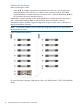
4 Node 16 Drive Enclosures (14S+2L) Before you begin cabling the storage system, carefully read or print the following section, including figures 1 and 2, “Identifying and Labeling the Components” (page 8).
Attach DP-1 Chains to Enclosures Red routing 1. 2. 3. 4. Connect Connect Connect Connect Node 0 (DP-1) to the I/O 0 (DP-1) on the A drive enclosure closest to the controller. all A drive enclosures from (DP-2) to (DP-1) working away from the controller. Node 2 (DP-1) to the I/O 0 (DP-1) on the C drive enclosure closest to the controller. all C drive enclosures from (DP-2) to (DP-1) working away from the controller. Green routing 1. 2. 3. 4.
Attach DP-2 Chains to Enclosures Red routing 1. 2. 3. 4. Connect Connect Connect Connect Node 0 (DP-2) to the I/O 0 (DP-1) on the B drive enclosure closest to the controller. all B drive enclosures from (DP-2) to (DP-1) working away from the controller. Node 2 (DP-2) to the I/O 0 (DP-1) on the D drive enclosure closest to the controller. all D drive enclosures from (DP-2) to (DP-1) working away from the controller. Green routing 1. 2. 3. 4.
Review Completed Cabling 4 Node 16 Drive Enclosures (14S+2L) 171
4 Node Interconnect Cabling The interconnection between Controller A (node pair 0/1), and Controller B (node pair 2/3) uses the four large interconnect cables. The cables are DIRECTIONAL and must be installed correctly for the system to function properly. Connect one cable at a time: 1. Controller A, Node 0, Intr 0 to Controller C, Node 2, Intr 1 2. Controller A, Node 0, Intr 1 to Controller C, Node 3, Intr 0 3. Controller A, Node 1, Intr 0 to Controller C, Node 3, Intr 1 4.
4 Node 18 Drive Enclosures (2S+16L) Before you begin cabling the storage system, carefully read or print the following section, including figures 1 and 2, “Identifying and Labeling the Components” (page 8).
Attach DP-1 Chains to Enclosures Red routing 1. 2. Connect Node 2 (DP-1) to the I/O 0 (DP-1) on the C drive enclosure closest to the controller. Connect all C drive enclosures from (DP-2) to (DP-1) working away from the controller. Green routing 1. 2. Connect Node 3 (DP-1) to I/O 1 (DP-1) on the C drive enclosure farthest from the controller. Connect all C drive enclosures from (DP-2) to (DP-1) working toward the controller. NOTE: 174 The two adjacent enclosures are not directly connected.
Attach DP-1 Chains to Enclosures Between Racks Six meter (6m) cables must be used for connections between racks. Red routing 1. 2. Connect Node 0 (DP-1) to the I/O 0 (DP-1) on the A drive enclosure closest to the controller. Connect all A drive enclosures from (DP-2) to (DP-1) working away from the controller. Green routing 1. 2. Connect Node 1 (DP-1) to I/O 1 (DP-1) on the A drive enclosure farthest from the controller. Connect all A drive enclosures from (DP-2) to (DP-1) working toward the controller.
Attach DP-2 Chains to Enclosures Red routing 1. 2. Connect Node 2 (DP-2) to the I/O 0 (DP-1) on the D drive enclosure closest to the controller. Connect all D drive enclosures from (DP-2) to (DP-1) working away from the controller. Green routing 1. 2. Connect Node 3 (DP-2) to I/O 1 (DP-1) on the D drive enclosure farthest from the controller. Connect all D drive enclosures from (DP-2) to (DP-1) working toward the controller. NOTE: 176 The two adjacent enclosures are not directly connected.
Attach DP-2 Chains to Enclosures Between Rack Six meter (6m) cables must be used for connections between racks. Red routing 1. 2. Connect Node 0 (DP-2) to the I/O 0 (DP-1) on the B drive enclosure closest to the controller. Connect all B drive enclosures from (DP-2) to (DP-1) working away from the controller. Green routing 1. 2. Connect Node 1 (DP-2) to I/O 1 (DP-1) on the B drive enclosure farthest from the controller. Connect all B drive enclosures from (DP-2) to (DP-1) working toward the controller.
Review Completed Cabling 178 Cabling HP 3PAR StoreServ 7000/7450
Review Completed Cabling Between Racks 4 Node 18 Drive Enclosures (2S+16L) 179
4 Node Interconnect Cabling The interconnection between Controller A (node pair 0/1), and Controller B (node pair 2/3) uses the four large interconnect cables. The cables are DIRECTIONAL and must be installed correctly for the system to function properly. Connect one cable at a time: 1. Controller A, Node 0, Intr 0 to Controller C, Node 2, Intr 1 2. Controller A, Node 0, Intr 1 to Controller C, Node 3, Intr 0 3. Controller A, Node 1, Intr 0 to Controller C, Node 3, Intr 1 4.
4 Node 18 Drive Enclosures (4S+14L) Before you begin cabling the storage system, carefully read or print the following section, including figures 1 and 2, “Identifying and Labeling the Components” (page 8).
Attach DP-1 Chains to Enclosures Red routing 1. 2. Connect Node 2 (DP-1) to the I/O 0 (DP-1) on the C drive enclosure closest to the controller. Connect all C drive enclosures from (DP-2) to (DP-1) working away from the controller. Green routing 1. 2. Connect Node 3 (DP-1) to I/O 1 (DP-1) on the C drive enclosure farthest from the controller. Connect all C drive enclosures from (DP-2) to (DP-1) working toward the controller. NOTE: 182 The two adjacent enclosures are not directly connected.
Attach DP-1 Chains to Enclosures Between Racks Six meter (6m) cables must be used for connections between racks. Red routing 1. 2. Connect Node 0 (DP-1) to the I/O 0 (DP-1) on the A drive enclosure closest to the controller. Connect all A drive enclosures from (DP-2) to (DP-1) working away from the controller. Green routing 1. 2. Connect Node 1 (DP-1) to I/O 1 (DP-1) on the A drive enclosure farthest from the controller. Connect all A drive enclosures from (DP-2) to (DP-1) working toward the controller.
Attach DP-2 Chains to Enclosures Red routing 1. 2. Connect Node 2 (DP-2) to the I/O 0 (DP-1) on the D drive enclosure closest to the controller. Connect all D drive enclosures from (DP-2) to (DP-1) working away from the controller. Green routing 1. 2. Connect Node 3 (DP-2) to I/O 1 (DP-1) on the D drive enclosure farthest from the controller. Connect all D drive enclosures from (DP-2) to (DP-1) working toward the controller. NOTE: The two adjacent enclosures are not directly connected.
Attach DP-2 Chains to Enclosures Between Rack Six meter (6m) cables must be used for connections between racks. Red routing 1. 2. Connect Node 0 (DP-2) to the I/O 0 (DP-1) on the B drive enclosure closest to the controller. Connect all B drive enclosures from (DP-2) to (DP-1) working away from the controller. Green routing 1. 2. Connect Node 1 (DP-2) to I/O 1 (DP-1) on the B drive enclosure farthest from the controller. Connect all B drive enclosures from (DP-2) to (DP-1) working toward the controller.
Review Completed Cabling 186 Cabling HP 3PAR StoreServ 7000/7450
Review Completed Cabling Between Racks 4 Node 18 Drive Enclosures (4S+14L) 187
4 Node Interconnect Cabling The interconnection between Controller A (node pair 0/1), and Controller B (node pair 2/3) uses the four large interconnect cables. The cables are DIRECTIONAL and must be installed correctly for the system to function properly. Connect one cable at a time: 1. Controller A, Node 0, Intr 0 to Controller C, Node 2, Intr 1 2. Controller A, Node 0, Intr 1 to Controller C, Node 3, Intr 0 3. Controller A, Node 1, Intr 0 to Controller C, Node 3, Intr 1 4.
4 Node 18 Drive Enclosures (6S+12L) Before you begin cabling the storage system, carefully read or print the following section, including figures 1 and 2, “Identifying and Labeling the Components” (page 8).
Attach DP-1 Chains to Enclosures Red routing 1. 2. Connect Node 2 (DP-1) to the I/O 0 (DP-1) on the C drive enclosure closest to the controller. Connect all C drive enclosures from (DP-2) to (DP-1) working away from the controller. Green routing 1. 2. Connect Node 3 (DP-1) to I/O 1 (DP-1) on the C drive enclosure farthest from the controller. Connect all C drive enclosures from (DP-2) to (DP-1) working toward the controller. NOTE: The two adjacent enclosures are not directly connected.
Attach DP-1 Chains to Enclosures Between Racks Six meter (6m) cables must be used for connections between racks. Red routing 1. 2. Connect Node 0 (DP-1) to the I/O 0 (DP-1) on the A drive enclosure closest to the controller. Connect all A drive enclosures from (DP-2) to (DP-1) working away from the controller. Green routing 1. 2. Connect Node 1 (DP-1) to I/O 1 (DP-1) on the A drive enclosure farthest from the controller. Connect all A drive enclosures from (DP-2) to (DP-1) working toward the controller.
Attach DP-2 Chains to Enclosures Red routing 1. 2. Connect Node 2 (DP-2) to the I/O 0 (DP-1) on the D drive enclosure closest to the controller. Connect all D drive enclosures from (DP-2) to (DP-1) working away from the controller. Green routing 1. 2. Connect Node 3 (DP-2) to I/O 1 (DP-1) on the D drive enclosure farthest from the controller. Connect all D drive enclosures from (DP-2) to (DP-1) working toward the controller. NOTE: The two adjacent enclosures are not directly connected.
Attach DP-2 Chains to Enclosures Between Rack Six meter (6m) cables must be used for connections between racks. Red routing 1. 2. Connect Node 0 (DP-2) to the I/O 0 (DP-1) on the B drive enclosure closest to the controller. Connect all B drive enclosures from (DP-2) to (DP-1) working away from the controller. Green routing 1. 2. Connect Node 1 (DP-2) to I/O 1 (DP-1) on the B drive enclosure farthest from the controller. Connect all B drive enclosures from (DP-2) to (DP-1) working toward the controller.
Review Completed Cabling 194 Cabling HP 3PAR StoreServ 7000/7450
Review Completed Cabling Between Racks 4 Node 18 Drive Enclosures (6S+12L) 195
4 Node Interconnect Cabling The interconnection between Controller A (node pair 0/1), and Controller B (node pair 2/3) uses the four large interconnect cables. The cables are DIRECTIONAL and must be installed correctly for the system to function properly. Connect one cable at a time: 1. Controller A, Node 0, Intr 0 to Controller C, Node 2, Intr 1 2. Controller A, Node 0, Intr 1 to Controller C, Node 3, Intr 0 3. Controller A, Node 1, Intr 0 to Controller C, Node 3, Intr 1 4.
4 Node 18 Drive Enclosures (8S+10L) Before you begin cabling the storage system, carefully read or print the following section, including figures 1 and 2, “Identifying and Labeling the Components” (page 8).
Attach DP-1 Chains to Enclosures Red routing 1. 2. Connect Node 2 (DP-1) to the I/O 0 (DP-1) on the C drive enclosure closest to the controller. Connect all C drive enclosures from (DP-2) to (DP-1) working away from the controller. Green routing 1. 2. Connect Node 3 (DP-1) to I/O 1 (DP-1) on the C drive enclosure farthest from the controller. Connect all C drive enclosures from (DP-2) to (DP-1) working toward the controller. NOTE: The two adjacent enclosures are not directly connected.
Attach DP-1 Chains to Enclosures Between Racks Six meter (6m) cables must be used for connections between racks. Red routing 1. 2. Connect Node 0 (DP-1) to the I/O 0 (DP-1) on the A drive enclosure closest to the controller. Connect all A drive enclosures from (DP-2) to (DP-1) working away from the controller. Green routing 1. 2. Connect Node 1 (DP-1) to I/O 1 (DP-1) on the A drive enclosure farthest from the controller. Connect all A drive enclosures from (DP-2) to (DP-1) working toward the controller.
Attach DP-2 Chains to Enclosures Red routing 1. 2. Connect Node 2 (DP-2) to the I/O 0 (DP-1) on the D drive enclosure closest to the controller. Connect all D drive enclosures from (DP-2) to (DP-1) working away from the controller. Green routing 1. 2. Connect Node 3 (DP-2) to I/O 1 (DP-1) on the D drive enclosure farthest from the controller. Connect all D drive enclosures from (DP-2) to (DP-1) working toward the controller. NOTE: The two adjacent enclosures are not directly connected.
Attach DP-2 Chains to Enclosures Between Rack Six meter (6m) cables must be used for connections between racks. Red routing 1. 2. Connect Node 0 (DP-2) to the I/O 0 (DP-1) on the B drive enclosure closest to the controller. Connect all B drive enclosures from (DP-2) to (DP-1) working away from the controller. Green routing 1. 2. Connect Node 1 (DP-2) to I/O 1 (DP-1) on the B drive enclosure farthest from the controller. Connect all B drive enclosures from (DP-2) to (DP-1) working toward the controller.
Review Completed Cabling 202 Cabling HP 3PAR StoreServ 7000/7450
Review Completed Cabling Between Racks 4 Node 18 Drive Enclosures (8S+10L) 203
4 Node Interconnect Cabling The interconnection between Controller A (node pair 0/1), and Controller B (node pair 2/3) uses the four large interconnect cables. The cables are DIRECTIONAL and must be installed correctly for the system to function properly. Connect one cable at a time: 1. Controller A, Node 0, Intr 0 to Controller C, Node 2, Intr 1 2. Controller A, Node 0, Intr 1 to Controller C, Node 3, Intr 0 3. Controller A, Node 1, Intr 0 to Controller C, Node 3, Intr 1 4.
4 Node 18 Drive Enclosures (10S+8L) Before you begin cabling the storage system, carefully read or print the following section, including figures 1 and 2, “Identifying and Labeling the Components” (page 8).
Attach DP-1 Chains to Enclosures Red routing 1. 2. Connect Node 2 (DP-1) to the I/O 0 (DP-1) on the C drive enclosure closest to the controller. Connect all C drive enclosures from (DP-2) to (DP-1) working away from the controller. Green routing 1. 2. Connect Node 3 (DP-1) to I/O 1 (DP-1) on the C drive enclosure farthest from the controller. Connect all C drive enclosures from (DP-2) to (DP-1) working toward the controller. NOTE: The two adjacent enclosures are not directly connected.
Attach DP-1 Chains to Enclosures Between Racks Six meter (6m) cables must be used for connections between racks. Red routing 1. 2. Connect Node 0 (DP-1) to the I/O 0 (DP-1) on the A drive enclosure closest to the controller. Connect all A drive enclosures from (DP-2) to (DP-1) working away from the controller. Green routing 1. 2. Connect Node 1 (DP-1) to I/O 1 (DP-1) on the A drive enclosure farthest from the controller. Connect all A drive enclosures from (DP-2) to (DP-1) working toward the controller.
Attach DP-2 Chains to Enclosures Red routing 1. 2. Connect Node 2 (DP-2) to the I/O 0 (DP-1) on the D drive enclosure closest to the controller. Connect all D drive enclosures from (DP-2) to (DP-1) working away from the controller. Green routing 1. 2. Connect Node 3 (DP-2) to I/O 1 (DP-1) on the D drive enclosure farthest from the controller. Connect all D drive enclosures from (DP-2) to (DP-1) working toward the controller. NOTE: The two adjacent enclosures are not directly connected.
Attach DP-2 Chains to Enclosures Between Racks Six meter (6m) cables must be used for connections between racks. Red routing 1. 2. Connect Node 0 (DP-2) to the I/O 0 (DP-1) on the B drive enclosure closest to the controller. Connect all B drive enclosures from (DP-2) to (DP-1) working away from the controller. Green routing 1. 2. Connect Node 1 (DP-2) to I/O 1 (DP-1) on the B drive enclosure farthest from the controller. Connect all B drive enclosures from (DP-2) to (DP-1) working toward the controller.
Review Completed Cabling 210 Cabling HP 3PAR StoreServ 7000/7450
Review Completed Cabling Between Racks 4 Node 18 Drive Enclosures (10S+8L) 211
Node Interconnect Cabling The interconnection between Controller A (node pair 0/1), and Controller B (node pair 2/3) uses the four large interconnect cables. The cables are DIRECTIONAL and must be installed correctly for the system to function properly. Connect one cable at a time: 1. Controller A, Node 0, Intr 0 to Controller C, Node 2, Intr 1 2. Controller A, Node 0, Intr 1 to Controller C, Node 3, Intr 0 3. Controller A, Node 1, Intr 0 to Controller C, Node 3, Intr 1 4.
4 Node 18 Drive Enclosures (12S+6L) Before you begin cabling the storage system, carefully read or print the following section, including figures 1 and 2, “Identifying and Labeling the Components” (page 8).
Attach DP-1 Chains to Enclosures Red routing 1. 2. Connect Node 2 (DP-1) to the I/O 0 (DP-1) on the C drive enclosure closest to the controller. Connect all C drive enclosures from (DP-2) to (DP-1) working away from the controller. Green routing 1. 2. Connect Node 3 (DP-1) to I/O 1 (DP-1) on the C drive enclosure farthest from the controller. Connect all C drive enclosures from (DP-2) to (DP-1) working toward the controller. NOTE: 214 The two adjacent enclosures are not directly connected.
Attach DP-1 Chains to Enclosures Between Racks Six meter (6m) cables must be used for connections between racks. Red routing 1. 2. Connect Node 0 (DP-1) to the I/O 0 (DP-1) on the A drive enclosure closest to the controller. Connect all A drive enclosures from (DP-2) to (DP-1) working away from the controller. Green routing 1. 2. Connect Node 1 (DP-1) to I/O 1 (DP-1) on the A drive enclosure farthest from the controller. Connect all A drive enclosures from (DP-2) to (DP-1) working toward the controller.
Attach DP-2 Chains to Enclosures Red routing 1. 2. Connect Node 2 (DP-2) to the I/O 0 (DP-1) on the D drive enclosure closest to the controller. Connect all D drive enclosures from (DP-2) to (DP-1) working away from the controller. Green routing 1. 2. Connect Node 3 (DP-2) to I/O 1 (DP-1) on the D drive enclosure farthest from the controller. Connect all D drive enclosures from (DP-2) to (DP-1) working toward the controller. NOTE: 216 The two adjacent enclosures are not directly connected.
Attach DP-2 Chains to Enclosures Between Rack Six meter (6m) cables must be used for connections between racks. Red routing 1. 2. Connect Node 0 (DP-2) to the I/O 0 (DP-1) on the B drive enclosure closest to the controller. Connect all B drive enclosures from (DP-2) to (DP-1) working away from the controller. Green routing 1. 2. Connect Node 1 (DP-2) to I/O 1 (DP-1) on the B drive enclosure farthest from the controller. Connect all B drive enclosures from (DP-2) to (DP-1) working toward the controller.
Review Completed Cabling 218 Cabling HP 3PAR StoreServ 7000/7450
Review Completed Cabling Between Racks 4 Node 18 Drive Enclosures (12S+6L) 219
4 Node Interconnect Cabling The interconnection between Controller A (node pair 0/1), and Controller B (node pair 2/3) uses the four large interconnect cables. The cables are DIRECTIONAL and must be installed correctly for the system to function properly. Connect one cable at a time: 1. Controller A, Node 0, Intr 0 to Controller C, Node 2, Intr 1 2. Controller A, Node 0, Intr 1 to Controller C, Node 3, Intr 0 3. Controller A, Node 1, Intr 0 to Controller C, Node 3, Intr 1 4.
4 Node 18 Drive Enclosures (14S+4L) Before you begin cabling the storage system, carefully read or print the following section, including figures 1 and 2, “Identifying and Labeling the Components” (page 8).
Attach DP-1 Chains to Enclosures Red routing 1. 2. Connect Node 2 (DP-1) to the I/O 0 (DP-1) on the C drive enclosure closest to the controller. Connect all C drive enclosures from (DP-2) to (DP-1) working away from the controller. Green routing 1. 2. Connect Node 3 (DP-1) to I/O 1 (DP-1) on the C drive enclosure farthest from the controller. Connect all C drive enclosures from (DP-2) to (DP-1) working toward the controller. NOTE: The two adjacent enclosures are not directly connected.
Attach DP-1 Chains to Enclosures Between Racks Six meter (6m) cables must be used for connections between racks. Red routing 1. 2. Connect Node 0 (DP-1) to the I/O 0 (DP-1) on the A drive enclosure closest to the controller. Connect all A drive enclosures from (DP-2) to (DP-1) working away from the controller. Green routing 1. 2. Connect Node 1 (DP-1) to I/O 1 (DP-1) on the A drive enclosure farthest from the controller. Connect all A drive enclosures from (DP-2) to (DP-1) working toward the controller.
Attach DP-2 Chains to Enclosures Red routing 1. 2. Connect Node 2 (DP-2) to the I/O 0 (DP-1) on the D drive enclosure closest to the controller. Connect all D drive enclosures from (DP-2) to (DP-1) working away from the controller. Green routing 1. 2. Connect Node 3 (DP-2) to I/O 1 (DP-1) on the D drive enclosure farthest from the controller. Connect all D drive enclosures from (DP-2) to (DP-1) working toward the controller. NOTE: The two adjacent enclosures are not directly connected.
Attach DP-2 Chains to Enclosures Between Rack Six meter (6m) cables must be used for connections between racks. Red routing 1. 2. Connect Node 0 (DP-2) to the I/O 0 (DP-1) on the B drive enclosure closest to the controller. Connect all B drive enclosures from (DP-2) to (DP-1) working away from the controller. Green routing 1. 2. Connect Node 1 (DP-2) to I/O 1 (DP-1) on the B drive enclosure farthest from the controller. Connect all B drive enclosures from (DP-2) to (DP-1) working toward the controller.
Review Completed Cabling 226 Cabling HP 3PAR StoreServ 7000/7450
Review Completed Cabling Between Racks 4 Node 18 Drive Enclosures (14S+4L) 227
4 Node Interconnect Cabling The interconnection between Controller A (node pair 0/1), and Controller B (node pair 2/3) uses the four large interconnect cables. The cables are DIRECTIONAL and must be installed correctly for the system to function properly. Connect one cable at a time: 1. Controller A, Node 0, Intr 0 to Controller C, Node 2, Intr 1 2. Controller A, Node 0, Intr 1 to Controller C, Node 3, Intr 0 3. Controller A, Node 1, Intr 0 to Controller C, Node 3, Intr 1 4.
4 Node 18 Drive Enclosures (16S+2L) Before you begin cabling the storage system, carefully read or print the following section, including figures 1 and 2, “Identifying and Labeling the Components” (page 8).
Attach DP-1 Chains to Enclosures Red routing 1. 2. Connect Node 2 (DP-1) to the I/O 0 (DP-1) on the C drive enclosure closest to the controller. Connect all C drive enclosures from (DP-2) to (DP-1) working away from the controller. Green routing 1. 2. Connect Node 3 (DP-1) to I/O 1 (DP-1) on the C drive enclosure farthest from the controller. Connect all C drive enclosures from (DP-2) to (DP-1) working toward the controller. NOTE: The two adjacent enclosures are not directly connected.
Attach DP-1 Chains to Enclosures Between Racks Six meter (6m) cables must be used for connections between racks. Red routing 1. 2. Connect Node 0 (DP-1) to the I/O 0 (DP-1) on the A drive enclosure closest to the controller. Connect all A drive enclosures from (DP-2) to (DP-1) working away from the controller. Green routing 1. 2. Connect Node 1 (DP-1) to I/O 1 (DP-1) on the A drive enclosure farthest from the controller. Connect all A drive enclosures from (DP-2) to (DP-1) working toward the controller.
Attach DP-2 Chains to Enclosures Red routing 1. 2. Connect Node 2 (DP-2) to the I/O 0 (DP-1) on the D drive enclosure closest to the controller. Connect all D drive enclosures from (DP-2) to (DP-1) working away from the controller. Green routing 1. 2. Connect Node 3 (DP-2) to I/O 1 (DP-1) on the D drive enclosure farthest from the controller. Connect all D drive enclosures from (DP-2) to (DP-1) working toward the controller. NOTE: The two adjacent enclosures are not directly connected.
Attach DP-2 Chains to Enclosures Between Rack Six meter (6m) cables must be used for connections between racks. Red routing 1. 2. Connect Node 0 (DP-2) to the I/O 0 (DP-1) on the B drive enclosure closest to the controller. Connect all B drive enclosures from (DP-2) to (DP-1) working away from the controller. Green routing 1. 2. Connect Node 1 (DP-2) to I/O 1 (DP-1) on the B drive enclosure farthest from the controller. Connect all B drive enclosures from (DP-2) to (DP-1) working toward the controller.
Review Completed Cabling 234 Cabling HP 3PAR StoreServ 7000/7450
Review Completed Cabling Between Racks 4 Node 18 Drive Enclosures (16S+2L) 235
4 Node Interconnect Cabling The interconnection between Controller A (node pair 0/1), and Controller B (node pair 2/3) uses the four large interconnect cables. The cables are DIRECTIONAL and must be installed correctly for the system to function properly. Connect one cable at a time: 1. Controller A, Node 0, Intr 0 to Controller C, Node 2, Intr 1 2. Controller A, Node 0, Intr 1 to Controller C, Node 3, Intr 0 3. Controller A, Node 1, Intr 0 to Controller C, Node 3, Intr 1 4.
3 Additional Resources and Related Documentation Contacting HP For worldwide technical support information, see the HP support website: http://www.hp.