HP 3PAR StoreServ 7450 Storage Site Planning Manual Abstract This manual provides information about installation planning and preparation for the HP 3PAR StoreServ 7450 Storage system. Use this document to obtain specific system configuration and installation guidelines for your storage system and operating site.
© Copyright 2014 Hewlett-Packard Development Company, L.P. The information contained herein is subject to change without notice. The only warranties for HP products and services are set forth in the express warranty statements accompanying such products and services. Nothing herein should be construed as constituting an additional warranty. HP shall not be liable for technical or editorial errors or omissions contained herein. Acknowledgments Microsoft® and Windows® are U.S.
Contents 1 System Components and Specifications.........................................................6 HP 3PAR StoreServ 7450 Storage System Components..................................................................6 StoreServ Storage Security Feature..............................................................................................9 Enhancing Security with Data Encryption................................................................................9 Storage System Specifications..........
Rack Space Considerations.................................................................................................30 Maintaining Minimum Clearances.......................................................................................30 Rack Mounting Kits.................................................................................................................31 Four-Post Shelf Kit...............................................................................................................
Dutch Recycling Notice.......................................................................................................47 Estonian Recycling Notice...................................................................................................48 Finnish Recycling Notice.....................................................................................................48 French Recycling Notice......................................................................................................
1 System Components and Specifications This chapter provides detailed system specifications for the HP 3PAR StoreServ 7450 Storage system and serves as a quick reference for other relevant specifications that are described in more detail in other chapters of this manual.
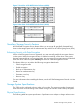
• Power Cooling Module is an integrated power supply, battery, and cooling fan. There are two types of PCMs: ◦ The 580 W is used in the drive enclosures and does not include a battery. ◦ The 764 W (includes a replaceable battery) is used in the node enclosures. The PCMs are located at the rear of the system, on either side of an enclosure. There are two PCMs per enclosure that are numbered from 0 to 1, from bottom to top and left to right.
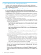
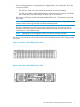
Figure 3 Front View of HP 3PAR StoreServ 7450 (Four-Node System) Figure 4 Rear View of HP 3PAR StoreServ 7450 (Four-Node System) Figure 5 Front View of HP M6710 Drive Enclosure (2U24) Figure 6 Rear View of HP M6710 Drive Enclosure (2U24) 8 System Components and Specifications
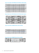
Figure 7 Front View of HP M6720 Drive Enclosure (4U24) Figure 8 Rear View of HP M6720 Drive Enclosure (4U24) StoreServ Storage Security Feature HP 3PAR Data Encryption security feature allows you to encrypt all specifically formatted hard drives on the storage system with an authentication key and the use of Self Encrypting Drives (SEDs). Enhancing Security with Data Encryption When a Data Encryption license is registered, you must manually enable the encryption feature on the system.
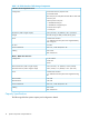
Table 1 HP 3PAR StoreServ 7450 Storage Components 7450 Drive/Node Integrated Enclosure Configuration 24 Small Form-Factor (SFF) drive slots 2 Controller Nodes PCIe slots (one per node) Fibre Channel HBA or iSCSI CNA 2 host FC ports 2 disk expansion SAS ports 1 1Gb Ethernet RCIP port 1 1Gb Ethernet management port 2 interconnect link ports 1 console port Dimensions (width x height x depth) 3.46” (87.9mm) x 19”(483mm) x 26.6” (674.9mm) Weight 48.7lbs/22.1kg (no HDD); 65.5lbs/29.
NOTE: SSDs have a limited number of writes that can occur before reaching the SSD's write endurance limit. This limit is generally high enough so wear out will not occur during the expected service life of an HP 3PAR StoreServ under the great majority of configurations, I/O patterns, and workloads. HP 3PAR StoreServ tracks all writes to SSDs and can report the percent of the total write endurance limit that has been used.
Power and Heat Specifications The following table lists the electrical power requirements. Table 3 Power Requirements Component Idle (watts/BTU/hr) Transactional (watts/BTU/hr) Node Pair, no drives, no add-on host adapters 236 W / 803 398 W / 1357 4-port 8 Gb/s Fibre Channel Adapter 24 W / 81.72 32.6 / 111 2-port 10 Gb/s iSCSI/FCoE Adapter 34 W / 115.77 40 W / 136.4 HP M6710 2.5 inch 2U SAS Drive Enclosure, no drives 150 / 512 (average) 150 / 512 (average) HP M6720 3.
Table 5 Required Cables Cable Type Connector Type Ethernet (Category 5) 3 cables minimum with 3 static IPs: RJ-45 • IP=SP • IP=StorageServ • IP For service (node rescue example) Multi-mode Fibre Channel Requires 50 micron OM3 cables LC-LC for 8–10Gb/s speeds. SAS cables for drive cage connections: 1M, 2M, and 6M Mini SAS SFF8088 The following table lists the typical Fibre Channel cable lengths required for a given type of connection.
2 General Site Planning Successful installation of the HP 3PAR StoreServ 7450 Storage system requires careful planning and supervision in collaboration with authorized HP representatives. Proper planning will help provide for a more efficient installation and greater reliability, availability, and serviceability. The chapter includes general recommendations for physical planning and site preparation for the storage system installation.
The following are suggested site planning tasks to be completed prior to the delivery and installation of the selected storage system. • Prepare a preliminary layout of the subsystem installation. • Review the power and the heating, ventilation, and air-conditioning (HVAC) requirements. • Order any additional support equipment indicated by the power and HVAC review.
• Disk drive magazine container: Height 38 inch (96.5 cm) x Width 29 inch (73.6 cm) x Depth 34 inch (86.4 cm) Approximate shipping weight: 392 lb (177.8 kg) • Node enclosure container: Height 30 inch (76.2 cm) x Width 35 inch (88.9 cm) x Depth 45 inch (114.3 cm) Approximate shipping weight: 618 lb (280.3 kg) When the equipment arrives, you must make sure that there is enough room to unload and unpack the storage system.
3 Structural/Environmental Considerations Consider the following when choosing or designing your facilities for the storage system: • Equipment location and layout that allows efficient use, easy maintenance, and future expansion. • Facility construction that provides a suitable operating environment, sufficient power, and adequate protection from fire, contamination, or other hazards. • Suitable temperatures and appropriate air quality that is free from environmental contaminants.
NOTE: For information on options available for the Intelligent Series Rack, refer to the Rack Options Catalog at www.hp.com/go/rackandpower. For information on rack requirements and considerations, see the Best practices for HP Intelligent Series Rack Family white paper. Meeting Environmental Conditions HP recommends that you maintain a controlled environment with a high degree of cleanliness, close control of temperature and humidity, and infrequent access by personnel.
normally required to replace moisture removed during the cooling process. The relative humidity for a subsystem equipment room should be set at 40%. This level is sufficient to suppress electromagnetic charge buildup, and low enough to avoid the risk of corrosion and condensation. To avoid air contamination from the humidifier, water treatment may be necessary in areas with high mineral content.
During major changes in the server room environment, special considerations must be taken into account whenever any drilling, sawing, welding, brazing, and so on, is performed. Precautions must be taken to prevent material particles (concrete or metal particles for example.) from becoming airborne. Storage systems should be powered down during construction that requires any drilling, sawing, welding, brazing, and so on. In addition, all debris must be removed before powering up the systems.
4 Power Requirements The following describes all power domains within a HP 3PAR StoreServ 7450 Storage systems. Electrical Requirements and Limitations Before physically installing a storage system, verify that the operating site has the necessary electrical circuitry. Each storage system requires four (200 - 240) Volt, 30 Amp outlets, or two outlets if only the bottom half of the rack is occupied. For proper redundant power protection, power should be supplied from two or more power sources.
labeled to identify the branch circuit it is controlling. The receptacle should also be labeled. Plan on a circuit breaker maximum of 30 A per PDU (de-rated to 24 A). Emergency Power Control As a safety precaution, you might consider providing emergency power-off controls for disconnecting the main service wiring that supplies storage systems.
There are two types of PCMs: • 580 W PCM - Used in HP M6720 and HP M6710 drive enclosures • 764 W PCM (includes a replaceable battery pack) - Used in controller node enclosures The following table provides the technical specifications of the replaceable battery located inside the 764 W PCM. Table 10 Battery Pack Technical Specifications Specifications Description Operating Temperature 41° to 104° F (5° to 40° C) - Reduce rating by 1° F for each 1000 ft altitude (1.
5 Network, Cabling, and Connectivity This chapter provides information about how to determine the best network configuration, including the necessary connections and cable routing options, when installing the storage system at a determined site. NOTE: The following information assumes that your are working with an established network, and explains how to connect a storage system to a network.
Table 11 TCP/IP Port Usage Table (continued) Port Usage Flow of Traffic • HP 3PAR Recovery Manager 3PAR CLI Server HP 3PAR Service Processor --> HP 3PAR CLI Server • HP 3PAR System Reporter • HP 3PAR Service Processor 5783: 3PAR Management Service with SSL (secured) Used by the following components for storage system monitoring and configuration over a secured channel: • HP 3PAR OS Management Console • HP 3PAR OS CLI • HP 3PAR Recovery Manager • HP 3PAR System Reporter 5785: 3PAR InForm Remote Copy
Required Cables The quantities and lengths of the cables required for storage system installation vary according to the specific storage system and network configuration. Fibre Channel cables are used externally to connect the controller node to the customer switch or host (in the case of a directly connected host). The SAS cables are used to connect the controller node to the drive enclosures. Table 12 Required Cables Cable Type Outside Diameter Connector Type SAS 6.60 – 7.
Table 14 Cable Limitations for Fibre Channel Host Connectivity Cable Size Speed Cable Length Limit 62.5 micron 2 Gb/s 100 meters 62.5 micron 4 Gb/s 70 meters 50 micron 2 Gb/s 300 meters 50 micron 4 Gb/s 150 meters Internal Cable Connections NOTE: For important exceptions to the cabling rules and guidelines described in this section, see the HP 3PAR OS Administrator’s Guide. The following table lists the typical SAS cable lengths required for a given type of connection.
Shared With a shared network topology, the storage system and SP share the internal customer network.
6 Third-Party/Existing Rack Mounting Some installations may use third-party or existing racks to house the HP 3PAR StoreServ 7450 Storage components. Install system components only into a standard 19-inch rack. The rack must also be equipped with the appropriate PDUs or power receptacles and have access to an adequate power source that provides the recommended level of redundancy.
Enclosure Installation • Two people are required to lift the enclosure during any servicing purposes. Service Limitations (Also applicable to third party rack installations) HP will not perform the following tasks: • Assemble the rack from components • Configure the rack hardware • Position the rack • Perform any extensive racking, re-racking, or cabling activities, including cabling activities involving conduits, raceways, patch panels, and movement or configuration of computer room floor panels.
Table 17 Minimum Clearances (continued) Doors: rack doors must be at least 1.5 inch (3.81 cm) away from the front and rear of the enclosures and be perforated with a minimum 50% open pattern across the entire surface. Cabling Front: n/a Rear: 30 inch (76.
7 Support and Other Resources Contacting HP For worldwide technical support information, see the HP support website: http://www.hp.
For information about: See: Migrating data from one HP 3PAR storage system to another HP 3PAR-to-3PAR Storage Peer Motion Guide Configuring the Secure Service Custodian server in order to monitor and control HP 3PAR storage systems HP 3PAR Secure Service Custodian Configuration Utility Reference Using the CLI to configure and manage HP 3PAR Remote Copy HP 3PAR Remote Copy Software User’s Guide Updating HP 3PAR operating systems HP 3PAR Upgrade Pre-Planning Guide Identifying storage system components
For information about: See: Planning for HP 3PAR storage system setup Hardware specifications, installation considerations, power requirements, networking options, and cabling information for HP 3PAR storage systems HP 3PAR 7200, 7400, and 7450 storage systems HP 3PAR StoreServ 7000 Storage Site Planning Manual HP 3PAR StoreServ 7450 Storage Site Planning Manual HP 3PAR 10000 storage systems HP 3PAR StoreServ 10000 Storage Physical Planning Manual HP 3PAR StoreServ 10000 Storage Third-Party Rack Physic
Typographic conventions Table 19 Document conventions Convention Element Bold text • Keys that you press • Text you typed into a GUI element, such as a text box • GUI elements that you click or select, such as menu items, buttons, and so on Monospace text • File and directory names • System output • Code • Commands, their arguments, and argument values • Code variables • Command variables Bold monospace text • Commands you enter into a command line interface • Syste
8 Documentation feedback HP is committed to providing documentation that meets your needs. To help us improve the documentation, send any errors, suggestions, or comments to Documentation Feedback (docsfeedback@hp.com). Include the document title and part number, version number, or the URL when submitting your feedback.
A Storage System Installation Checklist Use this chapter to complete all the requirements before you begin installing the storage system hardware and software.
Table 20 SP and Storage System Software Installation Checklist (continued) Custom duplex (half or full) and Custom speed (10, 100, or 1000 MB/s) Proxy server settings for Remote Support (if applicable): Protocol Address and port Authentication information (optional) Date and time: Enter manually Use NTP server information Time zone region New password to assign setupusr (for use with the system setup wizards) NOTE: All passwords for the setupusr username must be between 7 and 32 characters in length and can
Table 20 SP and Storage System Software Installation Checklist (continued) New password to assign 3paradm (to access the storage system) NOTE: Passwords for the 3paradm username can include all printable characters and be between 6-8 characters in length. HP 3PAR SmartStart Performing host configurations after using SmartStart for installation setup requires available server to run Microsoft Windows 2008 R2 x64 Edition or 2012.
B Regulatory Compliance Notices Regulatory Compliance Identification Numbers For the purpose of regulatory compliance certifications and identification, this product has been assigned a unique regulatory model number. The regulatory model number can be found on the product nameplate label, along with all required approval markings and information. When requesting compliance information for this product, always refer to this regulatory model number.
off and on, the user is encouraged to try to correct the interference by one or more of the following measures: • Reorient or relocate the receiving antenna. • Increase the separation between the equipment and receiver. • Connect the equipment into an outlet on a circuit that is different from the outlet to which the receiver is connected. • Consult the dealer or an experienced radio or television technician for help.
This compliance is indicated by the following conformity marking placed on the product: This marking is valid for non-Telecom products and EU harmonized Telecom products (e.g., Bluetooth). Certificates can be obtained from http://www.hp.com/go/certificates.
Class B Equipment Taiwanese Notices BSMI Class A Notice Taiwan Battery Recycle Statement Turkish Recycling Notice Türkiye Cumhuriyeti: EEE Yönetmeliğine Uygundur Vietnamese Information Technology and Communications Compliance Marking Taiwanese Notices 43
Laser Compliance Notices English Laser Notice This device may contain a laser that is classified as a Class 1 Laser Product in accordance with U.S. FDA regulations and the IEC 60825-1. The product does not emit hazardous laser radiation. WARNING! Use of controls or adjustments or performance of procedures other than those specified herein or in the laser product's installation guide may result in hazardous radiation exposure.
German Laser Notice Italian Laser Notice Japanese Laser Notice Laser Compliance Notices 45
Spanish Laser Notice Recycling Notices English Recycling Notice Disposal of waste equipment by users in private household in the European Union This symbol means do not dispose of your product with your other household waste. Instead, you should protect human health and the environment by handing over your waste equipment to a designated collection point for the recycling of waste electrical and electronic equipment.
Bulgarian Recycling Notice Изхвърляне на отпадъчно оборудване от потребители в частни домакинства в Европейския съюз Този символ върху продукта или опаковката му показва, че продуктът не трябва да се изхвърля заедно с другите битови отпадъци. Вместо това, трябва да предпазите човешкото здраве и околната среда, като предадете отпадъчното оборудване в предназначен за събирането му пункт за рециклиране на неизползваемо електрическо и електронно борудване.
Estonian Recycling Notice Äravisatavate seadmete likvideerimine Euroopa Liidu eramajapidamistes See märk näitab, et seadet ei tohi visata olmeprügi hulka. Inimeste tervise ja keskkonna säästmise nimel tuleb äravisatav toode tuua elektriliste ja elektrooniliste seadmete käitlemisega egelevasse kogumispunkti. Küsimuste korral pöörduge kohaliku prügikäitlusettevõtte poole.
Greek Recycling Notice Απόρριψη άχρηοτου εξοπλισμού από ιδιώτες χρήστες στην Ευρωπαϊκή Ένωση Αυτό το σύμβολο σημαίνει ότι δεν πρέπει να απορρίψετε το προϊόν με τα λοιπά οικιακά απορρίμματα. Αντίθετα, πρέπει να προστατέψετε την ανθρώπινη υγεία και το περιβάλλον παραδίδοντας τον άχρηστο εξοπλισμό σας σε εξουσιοδοτημένο σημείο συλλογής για την ανακύκλωση άχρηστου ηλεκτρικού και ηλεκτρονικού εξοπλισμού. Για περισσότερες πληροφορίες, επικοινωνήστε με την υπηρεσία απόρριψης απορριμμάτων της περιοχής σας.
Lithuanian Recycling Notice Nolietotu iekārtu iznīcināšanas noteikumi lietotājiem Eiropas Savienības privātajās mājsaimniecībās Šis simbols norāda, ka ierīci nedrīkst utilizēt kopā ar citiem mājsaimniecības atkritumiem. Jums jārūpējas par cilvēku veselības un vides aizsardzību, nododot lietoto aprīkojumu otrreizējai pārstrādei īpašā lietotu elektrisko un elektronisko ierīču savākšanas punktā. Lai iegūtu plašāku informāciju, lūdzu, sazinieties ar savu mājsaimniecības atkritumu likvidēšanas dienestu.
Slovak Recycling Notice Likvidácia vyradených zariadení používateľmi v domácnostiach v Európskej únii Tento symbol znamená, že tento produkt sa nemá likvidovať s ostatným domovým odpadom. Namiesto toho by ste mali chrániť ľudské zdravie a životné prostredie odovzdaním odpadového zariadenia na zbernom mieste, ktoré je určené na recykláciu odpadových elektrických a elektronických zariadení. Ďalšie informácie získate od spoločnosti zaoberajúcej sa likvidáciou domového odpadu.
French Battery Notice German Battery Notice 52 Regulatory Compliance Notices
Italian Battery Notice Japanese Battery Notice Battery Replacement Notices 53
Spanish Battery Notice 54 Regulatory Compliance Notices