
Module Installation Guide 2005-12


8
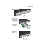
Installing the Module
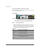
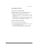
Verifying the Module is Installed Correctly
Observe the Module Status and Fault LEDs on the front of the switch to verify
the module is installed properly.
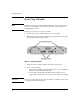
Figure 4. Location of Module Status LEDs
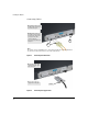
When the module is installed properly and the switch is powered on, or
the module is installed when the switch already has power, the module
undergoes a self test that takes a few seconds. You can use the LEDs to
determine that the module is installed properly and has passed the self
test, as described in the “LED Behavior” table below.
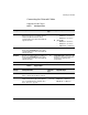
LED Behavior
LED Display for a Properly Installed Module
Mdl Status on the
front of the switch
The LED goes ON as soon as the module is installed and the switch
is powered on, and stays ON steadily.
Mdl Status on the
module
The LED goes ON as soon as the module is installed and the switch
is powered on, and stays ON steadily.
Fault OFF normal state, no fault condition exist.
Link (on the module) The LED goes ON to indicate the port is enabled, connected and
detects a signal from the attached device.
Activity (on the
module)
The LED blinks to show relative activity.
Fault
Power
Locator
LED
Mode
Clear
Reset
PoE-Integrated 1
0
Tes t
Tm p
Status
PoE
Fan
Usr
FDx
Spd
PoE
Act
*
10864
2
97
5
3
1
Link
Mode
Link
Mode
Console
Auxiliary Port
Status of the Back
Mdl
RPSEPS
ProCurve
Switch 3500yl
J8692A
Spd mode: off = 10 Mbps
flash = 100 Mbps
on = 1000 Mbps
*
PoE
*The Module Status LED is located in the same place on the 3500yl and 6200yl Switches.
Module Status LED*
Fault LED