HP 4400 Enterprise Virtual Array Expansion Rack Reference Guide Abstract This guide describes how to add an expansion rack to an EVA4400 main rack; it is intended for HP-authorized service personnel only.
© Copyright 2013 Hewlett-Packard Development Company, L.P. The information contained herein is subject to change without notice. The only warranties for HP products and services are set forth in the express warranty statements accompanying such products and services. Nothing herein should be construed as constituting an additional warranty. HP shall not be liable for technical or editorial errors or omissions contained herein.
Contents 1 Getting started...........................................................................................4 Hardware requirements.............................................................................................................4 Expansion rack requirements......................................................................................................4 2 Installing disk enclosures in the expansion rack...............................................6 Before you begin..............
1 Getting started First, decide what type of expansion you will perform; this will determine which hardware components are needed. • EVA4400 components—The EVA4400 can support a maximum of 8 disk enclosures (main and expansion racks combined). If the main rack containing the EVA4400 includes non-EVA components (such as servers or switches) is full, you can add an expansion rack. • EVA4400 2C8D main rack—The main rack is full with 2 controllers and 8 disk enclosures.
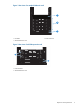
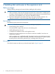
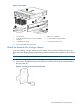
Figure 1 Rear view of a sample 2C4D main rack 1 2 3 1. Controller 2. Disk enclosures 3. Power distribution units Figure 2 Rear view of a 0C2D expansion rack 1 2 1. Disk enclosures 2.
2 Installing disk enclosures in the expansion rack Before you begin Read the following warnings and cautions before installing the disk enclosure. CAUTION: 1. Make sure that the cabinet and all equipment mounted in the cabinet have a reliable ground connection. Verify that the total current of the cabinet components does not exceed the current rating of the power distribution unit or the power distribution modules. 2. Parts can be damaged by electrostatic discharge. User proper anti-static protection.
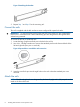
Figure 3 Kit contents 1. Disk enclosure 5. Rails with –03 brackets 2. Eight disk drive blanks (may come pre-installed in enclosure) 6. Two Fibre Channel copper cables 3. –04 brackets (not used) 7. Two enclosure power cords 4.
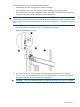
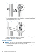
Figure 5 Attaching the brackets 3. Repeat Step 1 and Step 2 for the remaining rail. Convert the rails The rail kit supplied with the disk enclosure comes configured for square-hole racks. IMPORTANT: Do not remove the pins from the ends of the rails unless you are converting the rails for use in round-hole racks. These load-bearing pins are designed to fit through the holes without being removed. To convert the rails for a round-hole rack: 1.
Consider the following when installing the rail assembly: • Installing the rails does not require any tools for assembly. • HP recommends you install all the rail kits before installing any other components. • Ensure that the rails are level, particularly front to rear in their corresponding front and rear rail hole (U) locations, before installing any other components. WARNING! Before you begin, ensure that the rack is sufficiently stable.
Figure 8 Attaching the front rail 3. Loosen the locking nut (1, Figure 9 (page 10)) on the shipping retaining bracket (2) and slide the bracket to the farthest position on the rear of the rail. This moves the bracket out of the way to let you install the chassis in the rails. Figure 9 Locking nut and retaining bracket 4. 5. After attaching the rail, grab and move the rail gently to be sure it is firmly engaged in the rack and that all latches are engaged in the rack holes.
CAUTION: Follow industry-standard practices when handling hard drives. Internal storage media can be damaged when drives are shaken, dropped, or roughly placed on a work surface. When installing a hard drive, make sure it is fully seated in the drive bay. To remove a hard drive, press the release button and pull the drive only slightly out of the enclosure. Then, to allow time for the internal disk to stop rotating, wait approximately 10 seconds before completely removing the drive from the enclosure. 1.
3. Continue sliding the enclosure into the rack until the front edge is flush with the front of the rack (1, Figure 12 (page 12)). Tighten the enclosure thumbscrews into the rack (2), taking care to not strip the Phillips-head thumbscrews. Figure 12 Tighten disk enclosure thumbscrews 4. 5. Reattach the front bezel covers.
For example, if you have four enclosures and eight drives, you could install four drives in bay 1 of each enclosure and four drives in bay 2 of each enclosure. Do not install all the drives in enclosure 1 and leave the other enclosures empty. Figure 14 Disk drive bay numbering Follow these guidelines: 1. Install the largest disk drives first, continuing with sizes in descending order (for example, 1000 GB first, then 450 GB, down to 146 GB drives) balancing drives across the enclosures. 2.
2. Insert a drive blank into any slot without a disk drive (Figure 16 (page 14)). Push the drive blank in until you detect a click. Figure 16 Inserting a drive blank Cable the disk enclosures in the expansion rack Complete connections between the disk enclosures in the expansion rack before connecting to the controllers and disk enclosures in the main rack.
Inspect expansion rack disk drives After the expansion rack is powered up, ensure that all disk drives are fully engaged and seated in their associated enclosures. Observe the disk drive status indicators to ensure that the disks are working properly. The status indicators will be amber or blue depending on the condition of the disk enclosure. See Figure 18 (page 15) for the location of the disk drive indicators and Table 2 (page 15) for a description of the indicators.
Inspect the disk enclosure fan modules On the disk enclosure fan modules (2, Figure 19 (page 16)), check the fan status LEDs: • Green — Normal operation • Amber — Fault condition • Off — Fan unseated from connector or failed Figure 19 Fan module location — rear view of disk enclosure 1 2 3 1. Power supply 2. Fan 3.
3 Connecting the main rack to the expansion rack You can complete the connection between the main and expansion racks while the controllers are powered on (online) or off (offline). The offline method is preferred if downtime is available. Routing cables in the expansion rack NOTE: The cables used are Optical fiber channel cables supplied in the HP P6000 EVA 5m Expansion Cable Kit AP712A kit (four in the kit). • Route the cables along the side of each rack so they can be secured and kept out of the way.
Figure 20 Cabling for an 2C4D to 0C4D expansion LE Cabling and Labeling Diagram;2C4D – Host Rack LE Cabling and Labeling Diagram;0C4D – Expansion Rack TBM UID PS 1 PS 2 Cntrl 1 Cntrl 2 UID FP1 FP2 DP1 A DP1-B to P1 UID DP1 B FP1 DP1 A FP2 DP1 B Service Service 02 06 05 01 02 5m FC Jmpr Cable w/SFPs 5m FC Jmpr Cable w/SFPs DP1-B to P1 01 PS 1 FAN 1 I/O A I/O B FAN 2 UID 03 5m FC Jmpr Cable w/SFPs P1 P1 04 FAN 1 I/O A I/O B FAN 2 UID P1 PS 2 P1 Mfg 5m FC Jmpr Cable
1. Verify that each fabric Fibre Channel switch to which the HSV controllers are connected is powered up and fully booted. The power indicator on each switch should be on. If you must power up the SAN switches, wait for them to complete their power-on boot process before proceeding. This may take several minutes. NOTE: Before applying power to the rack, ensure that the power switch on each HSV controller is off. 2. 3. 4. 5. 6. 7. Power on the circuit breakers on both EVA rack PDUs.
4 Support and other resources Contacting HP HP technical support For worldwide technical support information, see the HP support website: http://www.hp.
Websites For additional information, see the following HP websites: • HP: http://www.hp.com • HP Storage: http://www.hp.com/go/storage • HP Partner Locator: http://www.hp.com/service_locator • HP Software Downloads: http://www.hp.com/support/manuals • HP Software Depot: http://h20293.www2.hp.com • HP Single Point of Connectivity Knowledge (SPOCK): http://www.hp.com/storage/spock • HP StorageWorks SAN manuals: http://www.hp.