HP 4400 Enterprise Virtual Array Installation Guide Abstract This guide describes how to install the HP 4400 Enterprise Virtual Array (EVA4400) and is intended for users with knowledge of storage area networks and basic operating system commands and utilities. The EVA4400 is customer self installable. However, you may purchase installation service by an HP-authorized service provider if preferred. For more information, contact HP technical support in North America at 1-800-474-6836.
© Copyright 2008, 2011 Hewlett-Packard Development Company, L.P. Confidential computer software. Valid license from HP required for possession, use, or copying. Consistent with FAR 12.211 and 12.212, Commercial Computer Software, Computer Software Documentation, and Technical Data for Commercial Items are licensed to the U.S. Government under vendor's standard commercial license. The information contained herein is subject to change without notice.
Contents 1 Review and confirm your plans.....................................................................5 Overview................................................................................................................................5 Prerequisites.............................................................................................................................5 Plan your storage configuration............................................................................................
7 Configuring servers using HP P6000 SmartStart...........................................29 Configuring management servers using HP P6000 SmartStart.......................................................29 Configuring application servers for Windows using HP P6000 SmartStart......................................29 8 Using and monitoring your storage.............................................................30 Using your storage.............................................................................
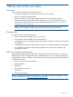
1 Review and confirm your plans Overview Before installing the EVA, HP recommends that you: • Develop an installation and configuration plan for your environment. • Review all videos and documentation. • Determine if the EVA will be fabric-attached (connected to Fibre Channel switch) or direct-attached (connected to Fibre Channel adapter in server). The EVA4400 is factory configured for fabric-attached. To change to direct-attached mode, see “Connecting to the management module” (page 25).
System and performance expectations To help determine the best way to configure your storage, rank the following three storage characteristics in order of importance: • Fault tolerance (high availability) • I/O performance • Storage efficiency With your priorities established, you can determine which striping method and RAID level to use.
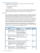
Table 1 Raid Level Comparison (continued) Summary Best practices Data redundancy RAID method of one. Vraid6 uses 33% more level of redundancy protection of all physical disk space than the Vraid types. Vraid0. NOTE: For best practice information, see the HP 4400 Enterprise Virtual Array configuration best practices white paper available at: http://h18006.www1.hp.com/storage/arraywhitepapers.
2 Prepare your site Overview Preparing your site means providing: • Physical rack space for the equipment • AC power for the EVA • Proper ventilation and temperature conditions • LAN or Fibre Channel cables to attach the EVA hardware to your network. To ensure continuous, safe, and reliable operation of your equipment, place your system in an approved environment. Consider using the HP Enterprise Configurator (eCO) to help plan and configure racks and rack-mountable devices.
Provide adequate and redundant sources of power Make sure that you have two high-line power feeds installed near your computer. These two power sources usually come from the same external power grid, but occasionally may originate from different grids or even entirely different sources. For protection against a power-source failure, obtain and include two uninterruptible power supplies in your installation. For power consumption specifications, see the QuickSpecs document at: http://www.hp.
3 Install components Overview Component installation includes: • Rail kits • Controller and disk enclosures • Disk drives NOTE: If you have ordered the factory integrated product, skip this chapter and go to “Turn on power” (page 20). Rack installation best practices In addition to industry-standard recommendations, consider the following: • Locate the heaviest items, such as uninterruptable power supplies (UPS) and additional disk enclosures near the bottom of the rack.
Figure 1 Typical EVA installed in rack (preferred layout) 1. Controller enclosure 2. Disk enclosures 3. PDU (at rear of enclosure) Attach the brackets for a longer chassis If you are installing a longer chassis into your cabinet, such as for the controller enclosure, you must remove the shipping retaining bracket and install the smaller brackets supplied in the accessory kit. NOTE: 1. 2. A No. 2 Phillips head screwdriver is required for this procedure.
Figure 3 Attaching the brackets 3. Repeat Step 1 and Step 2 for the remaining rail. Converting the rails The rail kit supplied with the disk enclosure comes configured for square-hole racks. IMPORTANT: Do not remove the pins from the ends of the rails unless you are converting the rails for use in round-hole racks. These load-bearing pins are designed to fit through the holes without being removed. To convert the rails for a round-hole rack: 1.
Consider the following when installing the rails: • Installing the rails does not require any tools for assembly. • HP recommends that you install all the rail kits before installing any other components. • Ensure that the rails are level before installing any other components. WARNING! Before you begin, ensure that the rack is sufficiently stable. If provided, lower the rack leveler feet and make sure any required stabilizers are installed. If provided, extend the anti-tip device.
Figure 6 Attaching the front rail 3. Loosen the locking nut (1, Figure 7 (page 14)) on the shipping retaining bracket (2) and slide the bracket to the farthest position on the rear of the rail. This moves the bracket out of the way to allow you to install the chassis in the rails. NOTE: Figure 7 (page 14) shows a disk enclosure rail and bracket.
Figure 8 Removing bezels from enclosure 2. Align the enclosure with the rails and slide it into the rack (Figure 9 (page 15)). Figure 9 Installing an enclosure (view from front of rack) 3. Continue sliding the enclosure into the rack until the front edge is flush with the front of the rack (1, Figure 10 (page 16)). Tighten the enclosure thumbscrews into the rack (2) taking care not to strip the thumbscrews.
Figure 10 Securing the rear of the enclosure in the rack (view from front of rack) 4. 5. Reattach the front bezel covers. At the rear of the rack, loosen the thumbscrew on the shipping retaining bracket (1, Figure 11 (page 16)) and slide the bracket forward (2) until the tab engages the slot in the chassis. Tighten the thumbscrew on the bracket. Figure 11 Securing the rear of the enclosure (view from rear of rack) 6. Repeat 1 through 5 to install the controller enclosures.
Figure 12 Disk drive numbering CAUTION: Install hard drives in the enclosures only after securing the enclosures in the rack: • An enclosure populated with hard drives is too heavy to lift safely. • Movement of an enclosure during installation might damage the internal storage media of installed hard drives. CAUTION: Follow industry-standard practices when handling hard drives. Internal storage media can be damaged when drives are shaken, dropped, or roughly placed on a work surface.
4 Connect cables and power cords Overview NOTE: If you have ordered the factory integrated product, skip this section and go to “Turn on power” (page 20). To connect cables and power cords: 1. Read the cabling best practices. 2. Attach Fibre Channel and/or LAN cables to controller, drives, and servers. 3. Label all cables using the supplied cable labeling kit. 4. Plug in all power cables. Cabling best practices • Use the shortest possible cable between devices.
Connecting Fibre Channel cables to the EVA (front end) See Figure 26 (page 38) and Figure 28 (page 39) in Appendix A for front end connections with server-based management. See Figure 27 (page 38) and Figure 29 (page 39) in Appendix A for front end connections with array-based management. Connecting cables to an HSV300-S controller enclosure (front end) See Figure 30 (page 40) for server-based management or Figure 31 (page 40) for array-based management in Appendix A.
5 Turn on power Power on the devices After the EVA and its disk enclosures are installed and connected to the SAN, power up all of the devices in the SAN and verify that they are operating properly. 1. Apply power to the power distribution unit (PDU) in the rack: 2. 3. 4. • If the controller enclosure was shipped with the power button in the ON position, the controller enclosure and connected disk enclosures will automatically power on.
Figure 14 EVA4400 front panel LEDs Table 3 EVA4400 status lights during startup Number LED function Startup condition Operating condition Fault condition 1 UID (Unit ID) Blinking blue Off—Blinking if turned N/A on remotely 2 Enclosure external health Blinking green Green 3 Enclosure fault warning Off Off Blinking amber 4 Link to host Solid amber Green Amber—Indicates link lost 5 (2 LEDs) Fan condition Solid amber Green Blinking green—Indicates charging or defective FRU 6 (2 LEDs
Figure 15 Rear and front view of the disk enclosure Verify the operating status of the Fibre Channel switches and adapters To verify that your switches are operating properly, view the switch LEDs and compare them with the patterns described in the documentation for these devices. If the LEDs indicate a fault, see the documentation that came with the switch for help.
NOTE: The embedded switch has an MDI-X port that supports straight-through or crossover Ethernet cables. Use a Cat 5e or greater cable. If needed, you can connect directly to the switch using the console port (2, Figure 16 (page 23)) and the provided console cable (manufacturing part number 259992–001). You may need a USB adapter for this cable if your laptop does not have a serial port. 2. Connect the Ethernet port (2, Figure 16 (page 23)) of the embedded switch to the laptop.
Figure 17 Switch Management GUI 4. 5. Change the IP address and other settings of the switch as appropriate for your network. You may also rename the switch or perform other configuration activities at this time. Remove the Ethernet cable from the first switch and connect the cable to the Ethernet port (2, Figure 16 (page 23)) of the other embedded switch. Browse to http://10.77.77.78 for the Controller 2 switch and repeat 4.
6 Connecting to the management module Overview This chapter describes several optional procedures. Complete the procedures in this chapter if any of the following situations apply. Otherwise, continue with “Configuring servers using HP P6000 SmartStart” (page 29). • Run HP P6000 Command View from the management module, which eliminates the requirement for a management server. • Change the default operating mode (via the HP P6000 Control Panel) for a direct connect configuration.
sets IP addresses of 192.168.0.1/24 (IPv4) and fd50:f2eb:a8a::7/48 (IPv6). If you are running a version earlier than HP Command View EVA 9.3 on the management module, the amber LED will flash momentarily when the reset is completed. IMPORTANT: At initial setup, you cannot browse to the HP P6000 Control Panel until you perform this step. 4. 5. Do one of the following: • Temporarily connect a LAN cable from a private network to the management module.
2. running a version earlier than HP Command View EVA 9.3 on the management module, the amber LED will flash momentarily when the reset is completed. Browse to https://192.168.0.1:2373 and log in as an HP administrator. HP recommends that you either change or delete the default IPv4 or IPv6 addresses to avoid duplicate address detection issues on your network. The default user name is admin. No password is required. The HP P6000 control panel GUI appears.
NOTE: Change your browser settings for the HP P6000 Control Panel window as described in the HP P6000 Command View Installation Guide. You must have administrator privilege to change the settings in the HP P6000 Control Panel. To change the default operating mode: 1. Connect to the management module using one of the methods described in “Connecting through a public network” (page 25) or “Connecting through a private network” (page 26). 2. Log into the HP P6000 Control Panel as an administrator.
7 Configuring servers using HP P6000 SmartStart Configuring management servers using HP P6000 SmartStart Use this procedure if you are connecting the EVA4400 to a management server for server-based management. To complete array configuration for array-based management, see “Completing the array configuration” in the HP P6000 Command View Installation Guide. 1. Insert the HP P6000 SmartStart CD in the drive of the management server. The HP P6000 SmartStart tool runs automatically. 2.
8 Using and monitoring your storage Using your storage To use the storage you have installed: 1. Start a server application. 2. Browse to a file system window and verify the drive letter of the virtual drive you have created. Firmware recovery A recovery CD containing the original XCS firmware installed on the array is shipped along with your EVA4400. The CD is only needed for recovery purposes. The latest firmware can be found on the HP software depot web page: http://h20392.www2.hp.
9 Support and other resources Contacting HP HP technical support For worldwide technical support information, see the HP support website: http://www.hp.
Related information Documents For documents referenced in this guide, see the Manuals page on the Business Support Center website: http://www.hp.com/support/manuals HP websites • HP: http://www.hp.com • HP Storage: http://www.hp.com/go/storage • HP Partner Locator: http://www.hp.com/service_locator • HP Software Downloads: http://www.hp.com/support/downloads • Hp Software Depot: http://www.software.hp.com • HP Single Point of Connectivity Knowledge (SPOCK): http://www.hp.
Typographic conventions Table 4 Document conventions Convention Uses Blue text: Table 4 (page 33) Cross-reference links and email addresses Blue, underlined text: http://www.hp.
Rack stability Rack stability protects personnel and equipment. WARNING! To reduce the risk of personal injury or damage to equipment: • Extend leveling jacks to the floor. • Ensure that the full weight of the rack rests on the leveling jacks. • Install stabilizing feet on the rack. • In multiple-rack installations, fasten racks together securely. • Extend only one rack component at a time. Racks can become unstable if more than one component is extended.
Figure 23 Location of WWN and serial number for bundled products Location of WWN and serial number 35
A EVA4400 cabling diagrams This appendix contains cabling diagrams for common EVA4400 installation environments. If you plan to configure the EVA4400 with an iSCSI device, see the HP P6000 iSCSI Connectivity User Guide. See Related information for the location of this guide. Connecting device port Fibre Channel cables to the EVA4400 (rear view) This section shows two views of how to connect cables to the controller.
Figure 25 Fibre Channel cabling for the EVA (rear view, mid-mounted controller) 1. This cable connects controller 1, device port 1B (top left—Cntrl 1, DP1B) to I/O module B, port 2 (bottom right—I/O B, P2). 2. This cable connects controller 2, device port 1A (top right—Cntrl 2, DP1A) to I/O module A, port 2 (bottom left—I/O A, P2). Connecting Fibre Channel cables to the EVA4400 (front end) You can cable the front end of your EVA4400 either to external Fibre Channel switches or directly to servers.
Figure 26 Cabling the controller to front end component—Fibre Channel to switch detail view with server-based management 1. File server 2. Management server 3. Database server 4. Fiber channel switch 5. LED status indicators for cabling connections to disk enclosures. See Figure 24 (page 36) and Figure 25 (page 37) for cabling connections. Figure 27 Cabling the controller to front end components—Fibre Channel to switch detail view with array-based management 1. File server 2. Database server 3.
Figure 28 Cabling the controller to front end components—Direct Fibre Channel to servers with server-based management 1. Management server 2. Database server 3. LED status indicators for cabling connections to disk enclosures. See Figure 24 (page 36) and Figure 25 (page 37) for cabling connections. Figure 29 Cabling the controller to front end component—direct Fibre Channel to servers with array-based management 1. File server 2. Database server 3. Indicates cabling connections to disk enclosures.
Figure 30 HSV300-S controller enclosure in an embedded Fibre Channel switch configuration with server-based management 1. Management server 2. Database server 3. Indicates cabling connections to disk enclosures. See Figure 24 (page 36) and Figure 25 (page 37) for cabling connections. Figure 31 HSV300-S controller enclosure in an embedded Fibre Channel switch configuration with array-based management 1. File server 2. Database server 3. Indicates cabling connections to disk enclosures.