HP EVA4400 M6412 drive enclosure installation instructions HP Part Number: 5697-0975 Published: June 2011 Edition: Second
© Copyright 2008, 2011 Hewlett-Packard Development Company, L.P.
About this document This document describes how to install an M6412 drive enclosure into a cabinet as part of an EVA4400 storage array. The drive enclosure installation may be performed while the array is in operation. NOTE: You can only add one disk enclosure online at a time. Before you begin Read the following warnings and cautions before installing the drive enclosure. WARNING! Make sure that the rack is sufficiently stable.
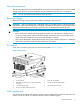
IMPORTANT: Do not remove the pins from the ends of the cabinet rails unless you are converting the rails for use in round-hole cabinets. These load-bearing pins are designed to fit through the holes without being removed. 1. 2. Locate the bag of eight round-hole pins that is included in the cabinet rail kit. Use a No. 2 Phillips screwdriver to remove the standard pins from the front and back of the left and right rails (four on each rail). See Figure 2 (page 4).
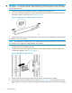
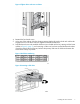
Figure 4 Installing front, right rail 5. Loosen the locking nut on the shipping retaining bracket (1, Figure 5 (page 5)) and slide the bracket to the farthest position on the rear of the rail (2). This moves the bracket out of the way to allow you to install the enclosure in the rails. Figure 5 Move back retaining bracket 6. 7. After attaching the rail, grab and move the rail gently to be sure it is firmly engaged in the cabinet and that all latches are engaged in the cabinet holes.
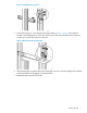
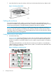
Installing the drive enclosure 1. Remove the bezel covers from each side of the enclosure (see Figure 6 (page 6)). CAUTION: Be careful when removing the bezel covers so as to not break the locking tabs that secure the covers to the enclosure. Figure 6 Bezel cover removal 2. Align the enclosure with the rails and slide it into the cabinet. Figure 7 Slide drive enclosure onto rails 3.
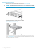
Figure 8 Tighten drive enclosure to cabinet 4. 5. 6. Reattach the front bezel covers. At the rear of the cabinet, slide the shipping retaining bracket forward on both rails until the tab engages the slot in the drive enclosure. Tighten the bracket thumbscrews. Populate the enclosure with available disk drives (not included with this kit), starting with the lowest number in Figure 9 (page 7), and continuing in order until you have inserted the desired number.
7. Insert drive blank into any slots without a disk drive. Push the drive blank until you detect a click. Figure 11 Inserting a drive blank Cabling the enclosure Two methods are described for cabling a new drive enclosure. The online method allows a drive enclosure to be added to a powered operational array. The offline method describes cabling an array that has been powered down. The offline method is preferred if downtime is available.
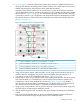
2. Figure 13 (page 9) shows the cabling when another drive enclosure is added to the bottom of the array. The dashed lines leading to the controller enclosure show cables that are moved, and dashed lines between the drive enclosures show cables that are added. Unplug the Fibre Channel cable from I/O module A port P2 of the drive enclosure nearest the newly installed drive enclosure, and plug it into the P2 port of I/O module A of the newly installed drive enclosure (1, Figure 13 (page 9)).
8. Power on any other drive enclosures attached to the array and visually check that the enclosures power on without errors. Wait at least one minute after all the enclosures are powered on for the drives to spin up and stabilize. 9. Power on the controller enclosure by pressing the power button on the power UID bezel until the enclosure responds (it may take up to 10 seconds for the controller enclosure to power on). Wait five minutes for the array to stabilize. 10.
7. 8. module B port 2 of the newly installed drive enclosure (3, Figure 13 (page 9)). In addition, a new Fibre Channel copper cable is installed between I/O Module B port P2 of the preexisting drive enclosure and I/O module B port 1 of the newly installed drive enclosure (4). Verify that I/O modules A and B on the added enclosure have been assigned an index number of the next higher enclosure number. For example, if the previous highest index number was “3,” then the installed enclosure should display “4.