HP BLc 4X DDR InfiniBand Gen 2 Switch Installation Guide for HP c-Class BladeSystems HP Part Number: 5992-5296 Published: October 2008 Edition: 1.
© Copyright 2008 Hewlett-Packard Development Company, L.P. The information contained herein is subject to change without notice. The only warranties for HP products and services are set forth in the express warranty statements accompanying such products and services. Nothing herein should be construed as constituting an additional warranty. HP shall not be liable for technical or editorial errors or omissions contained herein. Printed in the U.K.
Table of Contents 1 Preparing for Installation................................................................................................7 1.1 Audience...........................................................................................................................................7 1.2 Documentation Resources.................................................................................................................7 1.3 Kit Contents.........................................................
List of Figures 1-1 1-2 1-3 1-4 2-1 2-2 2-3 2-4 2-5 4-1 4-2 4-3 4 HP BLc 4X DDR InfiniBand Gen 2 Switch......................................................................................7 HP Onboard Administrator Screen Example.................................................................................8 HP BLc 4X DDR InfiniBand Gen 2 Switch Connector Bays............................................................8 HP BLc 4X DDR InfiniBand Gen 2 Switch LEDs.........................................
List of Tables 1-1 HP BLc 4X DDR InfiniBand Gen 2 Switch Descriptions and Status...............................................
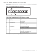
1 Preparing for Installation 1.1 Audience This document is intended for HP service representatives and other persons trained to install hardware options in HP BladeSystem configurations. Such persons are expected to understand the hazards of working in this environment and to take suitable precautions to minimize danger to themselves and others. 1.
For specific port connections for each server blade, see the HP BladeSystem Onboard Administrator User Guide. Connections differ by server blade type. The information contained in this document explains the cabling between the HP 4X DDR InfiniBand Gen 2 Switch and the network switches. The HP Onboard Administrator screen example (see Figure 1-2) is a reference for port mapping.
1.6 HP BLc 4X DDR InfiniBand Gen 2 Switch LEDs Figure 1-4 shows the LEDs and Table 1-1 describes the LEDS in the HP BLc 4X DDR InfiniBand Gen 2 Switch.
2 Hardware Installation This chapter contains the following sections: • Installing the HP BLc 4X DDR InfiniBand Gen 2 Switch (Section 2.1) • Installing InfiniBand cables in the HP BLc 4X DDR InfiniBand Gen 2 Switch (Section 2.2) • Cable Management (Section 2.3) • InfiniBand subnet managerment (Section 2.4) 2.1 Installing the HP BLc 4X DDR InfiniBand Gen 2 Switch To install the HP BLc 4X DDR InfiniBand Gen 2 Switch, follow the steps in Section 2.1.1 and Section 2.1.2.
2.1.2 Install the HP BLc 4X DDR InfiniBand Gen 2 Switch into the HP BladeSystem Enclosure To install the HP BLc 4X DDR InfiniBand Gen 2 Switch into the HP BladeSystem c7000 enclosure, follow these steps: 1. 2. Slide the HP BLc 4X DDR InfiniBand Gen 2 Switch all the way into the HP BladeSystem c7000 enclosure (see callout 1 in Figure 2-2). Push the blade handle in until it is in the locked position (see callout 2 in Figure 2-2).
Note: InfiniBand cables with QSFP to CX4 connectors are required when the HP BLc 4X DDR InfiniBand Gen 2 Switch uplinks to an InfiniBand spine interconnect with CX4 connectors. Figure 2-3 QSFP InfiniBand DDR/QDR Cable 2 3 1 The following list describes the callouts shown in Figure 2-3: 1. InfiniBand cable 2. QSFP connector release pull tab 3. QSFP connector Note: The InfiniBand cables are not included in this kit and must be purchased separately.
1. 2. 3. QSFP connector HP BLc 4X DDR InfiniBand Gen 2 Switch - port 1 InfiniBand cable Figure 2-5 InfiniBand Cable Installed in Port 1 of the HP BLc 4X DDR InfiniBand Gen 2 Switch 1 2 The following list describes the callouts shown in Figure 2-5: 1. InfiniBand cable installed in port 1 of the HP BLc 4X DDR InfiniBand Gen 2 Switch 2. HP BLc 4X DDR InfiniBand Gen 2 Switch You can install up to 16 InfiniBand cables in the HP BLc 4X DDR InfiniBand Gen 2 Switch.
Note: The c-Class cable management bracket is not included in this kit and must be ordered separately. 2.4 InfiniBand Subnet Management The HP BLc 4X DDR InfiniBand Gen 2 Switch does not have an embedded subnet manager. All InfiniBand networks require a subnet manager to manage, monitor and troubleshoot the InfiniBand fabric. A subnet manager is required for the HP BLc 4X DDR InfiniBand Gen 2 Switch.
3 Removing the HP BLc 4X DDR InfiniBand Gen 2 Switch for Service Put the HP 10K series rack and the HP BladeSystem c7000 enclosure into a safe and stable state for component removal and bring the component to an appropriate state for removal. You must ensure that you can reach the component easily and handle it safely. For more information about removing c-Class components from the c-Class enclosure, see the HP BladeSystem c7000 Enclosure Service and Maintenance Guide: http://h20000.www2.hp.
4 Regulatory Compliance The chapter lists all of the regulatory notices of compliance for the HP BLc 4X DDR InfiniBand Gen 2 Switch. 4.1 Regulatory Compliance Identification Numbers For the purpose of regulatory compliance certifications and identification, this product has been assigned a unique regulatory model number. The regulatory model number can be found on the product nameplate label, along with all required approval markings and information.
Figure 4-1 EU Declaration of Conformity Markings Hewlett-Packard GmbH, HQ-TRE, Herrenberger Strasse 140, 71034 Boeblingen, Germany 4.7 Japanese Notice Figure 4-2 Japanese Notice 4.
*5992-5296* Printed in the U.K.