HP BLc QLogic 4X QDR InfiniBand Managed Switch and InfiniBand Switch Management Module Installation Guide for HP c-Class BladeSystems HP Part Number: QL-HWINS-1A Published: Nov.
© Copyright 2009 Hewlett-Packard Development Company, L.P. The information contained herein is subject to change without notice. The only warranties for HP products and services are set forth in the express warranty statements accompanying such products and services. Nothing herein should be construed as constituting an additional warranty. HP shall not be liable for technical or editorial errors or omissions contained herein.
Contents 1 Preparing for Installation . . . . . . . . . . . . . . . . . . . . . . . . . . . . . . . . . . . . . . . . . . . . . . . 5 Audience. . . . . . . . . . . . . . . . . . . . . . . . . . . . . . . . . . . . . . . . . . . . . . . . . . . . . . . . . . . . . . . . Documentation Resources . . . . . . . . . . . . . . . . . . . . . . . . . . . . . . . . . . . . . . . . . . . . . . . . . . . . Kit Contents . . . . . . . . . . . . . . . . . . . . . . . . . . . . . . . . . . . . . . . . . . . . . . . . . . .
1 Preparing for Installation Audience This document is intended for HP service representatives and other persons trained to install hardware options in HP BladeSystem configurations. Such persons are expected to understand the hazards of working in this environment and to take suitable precautions to minimize danger to themselves and others.
Additional Information Mezzanine card installation determines bay assignments for interconnect module installation.
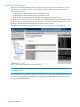
Connectors Figure 3 shows the Quad Small Form-factor Pluggable (QSFP) connector ports and Table 1 describes the connectors on the front panel of the QLogic BLc 4X QDR InfiniBand Switch.
Preparing for Installation
2 Hardware Installation This chapter contains the following sections: • ”Installing an HP BLc QLogic 4X QDR InfiniBand Managed Switch” • ”Installing InfiniBand Cables in an HP BLc QLogic 4X QDR InfiniBand Managed Switch” • ”Removing an InfiniBand Cable from the HP BLc QLogic 4X QDR InfiniBand Managed Switch” • ”InfiniBand Subnet Management” Installing an HP BLc QLogic 4X QDR InfiniBand Managed Switch To install an HP BLc QLogic 4X QDR InfiniBand Managed Switch, follow the steps in the following subsectio
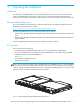
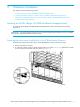
Installing an HP BLc QLogic 4X QDR InfiniBand Managed Switch into an HP BladeSystem Enclosure To install an HP BLc QLogic 4X QDR InfiniBand Managed Switch into an HP BladeSystem enclosure, follow these steps: 1. Slide the HP BLc QLogic 4X QDR InfiniBand Managed Switch all the way into the HP BladeSystem enclosure (see callout 1 in Figure 6). Figure 6 Installing an HP BLc QLogic 4X QDR InfiniBand Managed Switch into an HP BladeSystem Enclosure 2.
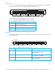
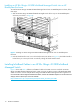
Figure 7 QSFP InfiniBand QDR/QDR Cable QSFP InfiniBand QDR/QDR Cable Table 3 Item Number NOTE: Description 1 InfiniBand cable 2 QSFP connector release pull tab 3 QSFP connector The InfiniBand cables are not included in this kit and must be purchased separately. When the HP BLc QLogic 4X QDR InfiniBand Managed Switches are connected together with the QSFP to QSFP InfiniBand cables it forms an InfiniBand high-performance network (also referred to as an InfiniBand fabric).
1. Align the InfiniBand cable QSFP connector (see callout 1 in Figure 8) with the HP BLc QLogic 4X QDR InfiniBand Managed Switch port (see callout 2 in Figure 8). Figure 8 Install InfiniBand Cable in an HP BLc QLogic 4X QDR InfiniBand Managed Switch Port 2. Insert the QSFP connector into the HP BLc QLogic 4X QDR InfiniBand Managed Switch port (see callout 1 in Figure 9) until it is fully engaged and locked.
The QLogic Fabric Manager is required for managing and troubleshooting an HP BLc QLogic 4X QDR InfiniBand Managed Switch. A subnet manager can be host-based (installed and run on a host node connected to the InfiniBand fabric). You can also use a switch-based subnet manager when certain managed switches are incorporated into the InfiniBand fabric. For more information about InfiniBand subnet management, see the InfiniBand interconnect documentation that came with your system or cluster.
Hardware Installation
3 Hardware Removal Put the HP BladeSystem enclosure into a safe and stable state for component removal and bring the component to an appropriate state for removal. You must ensure that you can reach the component easily and handle it safely. For more information about removing c-Class components from the c-Class enclosure, see the HP BladeSystem Enclosure Service and Maintenance Guide: http://h20000.www2.hp.com/bc/docs/support/SupportManual/c00714237/c00714237.
Hardware Removal
4 Regulatory Compliance The chapter lists all of the regulatory notices of compliance for the HP BLc QLogic 4X QDR InfiniBand Managed Switch. Regulatory Compliance Identification Numbers For the purpose of regulatory compliance certifications and identification, this product has been assigned a unique regulatory model number. The regulatory model number can be found on the product nameplate label, along with all required approval markings and information.
This compliance is indicated by the following conformity marking placed on the product: T his mark ing is val id for no n-Teleco m prod uct s and EU harmo nized Telecom p ro ducts (e.g. Bluet oot h). xxxx* This marking is valid for EU non -harmonized Telecom product s .
A Installation of Switch Management Module This appendix provides the procedures for installing the Switch Management Module. The Switch Management Module is not a Field Replaceable Unit (FRU) and is installed in the managed version of the HP BLc QLogic 4X QDR InfiniBand Managed Switch. To install the Switch Management Module in an HP BLc QLogic 4X QDR InfiniBand Managed Switch, follow the steps below: 1.
1 Figure 12 Switch with Switch Management Module 20 Installation of Switch Management Module
4. Close cover slowly, ensuring that the module connectors (see callout 1 in Figure 11) connect to the motherboard connectors (see callout 1 in Figure 13). 1 Figure 13 Switch with Switch Management Module Cover Removed 5. Replace the screw that was removed in step 1 (see callout 1 in Figure 10) and tighten securely.
Installation of Switch Management Module
*QL-HWINS-1A* QL-HWINS-1A
Figures 1 2 3 4 5 6 7 8 9 10 11 12 13 HP BLc QLogic 4X QDR InfiniBand Managed Switch . . . . . . . . . . . . . . . . . . . . . . . . . . . . . . . . . . . . 5 HP Onboard Administrator Screen Example . . . . . . . . . . . . . . . . . . . . . . . . . . . . . . . . . . . . . . . . . . 6 QLogic BLc 4X QDR InfiniBand Switch Connector Ports. . . . . . . . . . . . . . . . . . . . . . . . . . . . . . . . . . . 7 QLogic BLc 4X QDR InfiniBand Switch Indicators . . . . . . . . . . . . . . . . . . . . . . . . . . . .
Tables 1 2 3 QLogic BLc 4X QDR InfiniBand Switch Connector Ports . . . . . . . . . . . . . . . . . . . . . . . . . . . . . . . . . . . 7 QLogic BLc 4X QDR InfiniBand Switch Indicators . . . . . . . . . . . . . . . . . . . . . . . . . . . . . . . . . . . . . . . . 7 QSFP InfiniBand QDR/QDR Cable . . . . . . . . . . . . . . . . . . . . . . . . . . . . . . . . . . . . . . . . . . . . . . . .