
HP BLc QLogic 4X QDR InfiniBand Managed Switch and InfiniBand Switch Management Module Installation Guide for HP c-Class BladeSystems


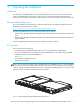
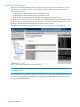
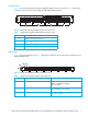

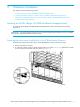
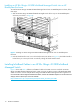
Table Of Contents
- Contents
- Preparing for Installation
- Hardware Installation
- Installing an HP BLc QLogic 4X QDR InfiniBand Managed Switch
- Installing InfiniBand Cables in an HP BLc QLogic 4X QDR InfiniBand Managed Switch
- Removing an InfiniBand Cable from the HP BLc QLogic 4X QDR InfiniBand Managed Switch
- InfiniBand Subnet Management
- Hardware Removal
- Regulatory Compliance
- Installation of Switch Management Module
HP BLc QLogic 4X QDR InfiniBand Managed Switch and InfiniBand Switch Management Module Installation Guide 7
Connectors
Figure 3 shows the Quad Small Form-factor Pluggable (QSFP) connector ports and Table 1 describes the
connectors on the front panel of the QLogic BLc 4X QDR InfiniBand Switch.
Figure 3 QLogic BLc 4X QDR InfiniBand Switch Connector Ports
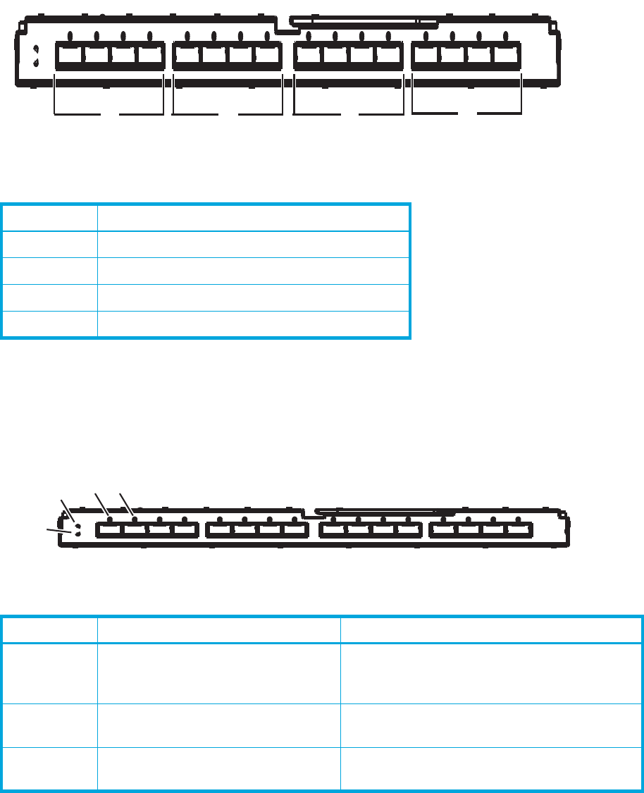
Indicators
Figure 4 shows the Indicators and Table 2 describes the indicators on the front panel of a QLogic BLc 4X
QDR InfiniBand Switch.
Figure 4 QLogic BLc 4X QDR InfiniBand Switch Indicators
Table 1 QLogic BLc 4X QDR InfiniBand Switch Connector Ports
Item Number Description
1 Uplink connectors, ports 1-4
2 Uplink connectors, ports 5-8
3 Uplink connectors, ports 9-12
4 Uplink connectors, ports 13-16
Table 2 QLogic BLc 4X QDR InfiniBand Switch Indicators
Item Number Description Status
1 Module Status Green = Normal operation
Amber = Degraded condition
Off = Power off
2 Module locator (UID)
Blue = Module ID selected
Off = Module ID not selected
3 Port state Green = Port is active
Off = Port not active