HP 501 802.11ac Wireless Client Bridge Configuration and Administration Guide Abstract This document describes how to configure and maintain an HP 501Wireless Client Bridge (J9835A). It is intended for system and network administrators.
© Copyright 2013 Hewlett-Packard Development Company, L.P. The information contained herein is subject to change without notice. The only warranties for HP products and services are set forth in the express warranty statements accompanying such products and services. Nothing herein should be construed as constituting an additional warranty. HP shall not be liable for technical or editorial errors or omissions contained herein. Acknowledgments Microsoft® and Windows® are U.
Contents 1 Deploying the HP 501 ................................................................................. 5 Using work group bridge mode to connect wired computers to a wireless network............................................. 5 Connecting a wired device using MAC address cloning................................................................................. 6 Connecting a serial device to a wireless network........................................................................................
Software upgrade.............................................................................................................................. 45 System information .................................................................................................................................. 46 6 Tools........................................................................................................ 47 System log ......................................................................................
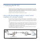
1 Deploying the HP 501 The HP 501 securely connects legacy Ethernet or serial communications devices to a wireless local area network (WLAN). It enables the deployment of legacy client devices, such as pointof-sale terminals, servers, and printers, in any location where a WLAN signal is available, thus eliminating the need to install a cabling infrastructure. The following sections describe various deployment scenarios.
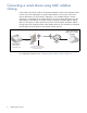
Connecting a wired device using MAC address cloning In this scenario, the HP 501 makes a wired printer available to clients on the upstream wireless network. Prior to this deployment, the printer’s MAC address was known by users from its previous placement on a wired network. Although it is now available through a wireless connection, it is preferable for the wireless clients to continue accessing the printer using the MAC address, so that they do not need to change any settings.
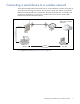
Connecting a serial device to a wireless network TCP serial functionality allows devices that have no no native Ethernet or wireless connectivity to access the network through a serial port. In this scenario, the HP 501 enables a point-of-sale terminal to exchange traffic with a remote host. The point-of-sale terminal is connected to the serial port on the HP 501. To connect it to a wireless network, the HP 501 converts traffic between the serial data format and TCP/IP.
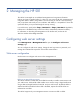
2 Managing the HP 501 The HP 501 is managed via its web-based management tool using Microsoft Internet Explorer 8 or later or Mozilla Firefox 17 or later. You can access the HP 501 management tool using either HTTP or HTTPS. Using HTTPS is more secure but you will see a security warning until you purchase and install your own certificate. With HTTPS, it is acceptable to choose the option that allows you to proceed through the security warning. In a web browser, specify either: http://192.168.1.
HTTPS port/HTTP port By default, the HTTP server uses the well-known logical port number 80 for communication with clients and the HTTPS port uses port number 443. You can specify different port numbers in the range 1025 to 65535 if the default ports are blocked or used for other protocols on your network. Session timeout If there is no activity on the management session for the specified time, then the administrator will be automatically logged off. The default timeout is 5 minutes.
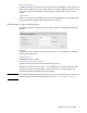
Managing HTTP SSL certificates When HTTPS access is enabled, the HP 501 must be able to present a Secure Sockets Layer (SSL) certificate to the web browser of a computer that attempts access to the management tool. The certificate assures that the browser is accessing the HP 501 with the specified IP address. It also provides information that the HP 501 and management computer use to encrypt their communication. A default certificate is present on the HP 501, based on the default device IP address 192.168.
Certificate issuer common name The common name attribute of the server certificate. The common name is often the fully qualified domain name for the HTTP server, or the IP address equivalent. Updating the certificate You can generate a new certificate directly using the HP 501 management tool, or you can upload a certificate to the HP 501 from a computer or network location. To generate a new certificate from the Management tool page, under Generate certificate, click Generate.
Configuring a management access control list You can create an access control list (ACL) that lists hosts that are authorized to access the HP 501 management tool. If this feature is disabled, anyone can access the management interface from any network client by supplying the correct user name and password. To enable the ACL feature: 1. Select Management > Management ACL to open the Management access control list configuration page. 2. Under Management ACL control, select Enabled. 3.
Configuring SNMP Simple Network Management Protocol (SNMP) defines a standard for recording, storing, and sharing information about network devices. SNMP facilitates network management, troubleshooting, and maintenance. The HP 501 supports SNMP versions 1, 2, and 3. Key components of any SNMP-managed network are managed devices, SNMP agents, and a management system. The agents store data about their devices in management information bases (MIBs) and return this data to the SNMP manager when requested.
System settings Under System settings, you can define basic properties of the HP 501 as an SNMP managed device. System name Enter a name to identify the HP 501 as an SNMP managed device (63 alphanumeric characters maximum). The default SNMP name is the product serial number. System location Enter a description of the physical location of the device (255 alphanumeric characters maximum). System contact Specify an email address for a contact person for the HP 501 (255 alphanumeric characters maximum).
SNMP source enable Select Enabled if you want to restrict the source of permitted SNMP requests to a specified IP address, hostname, or subnet. When disabled, the HP 501 accepts requests from any device on the network that is configured with the appropriate community name. It is disabled by default. Hostname, address, or subnet If you have enabled the SNMP source enable setting, specify the hostname or IPv4 address of a device to enable it to execute get and set requests to the HP 501.
SNMPv3 configuration SNMPv3 adds security in the form of configurable encryption of data and enhanced authentication of users. You can configure security settings on a per-user basis. You can also configure a user as an SNMPv3 receiver, so that the HP 501 sends SNMP trap messages to the user. Configuring SNMPv3 users The SNMPv3 users page enables the network administrator to define multiple user IDs with different privileges and security levels.
To remove a configured SNMPv3 user, select the name in the SNMPv3 user list, and then click Remove. Configuring SNMPv3 receivers The HP 501 can send SNMP traps to configured SNMPv3 users. The eligible users must be configured on the SNMPv3 users page. On the SNMPv3 receivers page, you provide IP information for the users you select to receive traps. To configure an SNMPv3 receiver: 1. In the management tool, select Management > SNMPv3 receivers. 2.
• INET-ADDRESS-MIB • SNMPv2-TM • RFC1155-SMI • RFC4688 • RFC1213-MIB • IP-MIB • RFC1215 • TCP-MIB • SNMP-FRAMEWORK-MIB • UDP-MIB • SNMP-NOTIFICATION-MIB • UCD-SNMP-MIB • SNMP-TARGET-MIB Private MIBs The HP 501 supports a private MIB named HP-WLAN-ACCESS-POINT-MIB, with the following organization and contact information: ORGANIZATION: HP Networking CONTACT-INFO: Hewlett Packard Company 8000 Foothills Blvd. Roseville, CA 95747 This private MIB is linked to an HP product MIB tree at: 1.3.6.1.
Setting the system time 19
Set system time This section displays the current system time. You can configure the time manually or have it automatically configured by a Network Time Protocol (NTP) server. Manually Select the date, time (in 24-hour notation), and timezone. Using network time protocol (NTP) NTP servers transmit Coordinated Universal Time (UTC, also known as Greenwich Mean Time) to their client systems. NTP sends periodic time requests to servers, using the returned time stamp to adjust its clock.
3 Wireless configuration Wireless range At high power, the HP 501 can communicate with APs that are up to about 300 feet away. The achievable range can vary widely depending on the antenna selected, the radio mode, and environmental and other circumstances. The following factors can affect wireless performance: • Radio power: More radio power means better signal quality and the ability to create bigger wireless cells.
Configuring radio settings To configure the HP 501 radio, select Wireless > Radio. The Modify radio settings page appears. This page enables you to configure the country in which the HP 501 operates, basic radio settings, such as the radio mode, and advanced radio features. Country The country of operation, also known as the regulatory domain, determines the availability of certain wireless settings on the HP 501.
5 GHz bands and is capable of connecting with 802.11a/b/g/n/ac APs. This is the default setting. • IEEE 802.11a: The HP 501 can connect to an 802.11a or 802.11 a/n/ac AP as an 802.11a client. • IEEE 802.11b/g: (Compatibility mode.) The HP 501 can connect to an 802.11b/g or 802.11b/g/n AP as an 802.11b/g client. • IEEE 802.11b/g/n: (Compatibility mode.) The HP 501 can connect to an 802.11b, 802.11g, or 802.11b/g/n AP as an 802.11b/g/n client. • IEEE 802.11a/n/ac: (Compatibility mode.
If multiple APs are detected with a stronger signal, preference is given to APs in the 5 GHz band over those in the 2.4 GHz band. The detected strength of each 5 GHz AP is increased by 10 dBm for comparison purposes only. The following examples illustrate the decision process and assume that the Mode is set to Auto.
RTS threshold Specify a Request to Send (RTS) threshold value from 0 to 2347. The default is 2347 octets. To ensure that sufficient bandwidth is available to send a frame, the HP 501 can send an RTS packet to the upstream AP and await for a Clear to Send (CTS) reply. When the HP 501 receives the CTS, it sends the frame. The RTS/CTS handshake itself consumes bandwidth, so it is generally not desirable to perform the handshake prior to a large percentage of data exchanges.
Configuring work group bridge mode To configure work group bridge mode, in the management tool select Wireless > Work group bridge. You can configure the following settings on the Work group bridge configuration page. Work group bridge mode Select Enable to configure this mode. It is disabled by default. SSID Specify the SSID of the wireless network to be bridged with the wired network. You can click the icon to the right of the text box to select an SSID from a list of available wireless networks.
Note WPA2 is used for 802.11n or 802.11ac operation. WPA is used for 802.11a/b/g (legacy) operation. Key Specify the preshared key (PSK) configured on the upstream AP. The key must be from 8 to 63 alphanumeric characters. Re-enter the key in the Confirm key box. WPA/WPA2 Enterprise Select this option if the upstream AP uses a remote authentication server to handle authentication requests.
Static WEP This method uses a WEP key that is configured on both the HP 501 and the upstream AP. It is the least secure method of protecting wireless transmissions. WEP is provided so you can authenticate with an upstream AP that does not support WPA. Note WEP cannot be used when the radio operating mode supports 802.11a/n/ac or 802.11n.
Configuring wireless bridging features Configuring MAC address cloning The HP 501 supports cloning the MAC address of a single connected wired device, thereby minimizing the impact on the network configuration when the device is converted to wireless. MAC cloning is useful when the upstream AP does not accept requests for more than one IP address per wireless MAC address. It also allows remote devices upstream to access the connected wired device by its MAC address.
• Management tool (TCP ports 80 and 443) • SNMP agent (UDP port 161) • Network time (UDP port 123) Redirecting unsupported traffic The HP 501 sends and receives only IPv4 traffic on the wireless link. By default, all other traffic is unsupported and is dropped. In some cases, you might want to forward the unsupported traffic to a wired device connected to the Ethernet port.
This feature is disabled by default. To enable, select Enabled, and then click Save. Note The DHCP relay agent feature is not supported when MAC address cloning is enabled. IP forwarding Ethernet devices that do not send any IP packets at startup have no entry in the HP 501 wireless-to-MAC translation table. As a result, the HP 501 cannot route incoming IPv4 wireless traffic to these devices.
Field Description Privacy Indicates whether there is any security enabled on the neighboring AP. • Off indicates that no security is enabled on the AP. • On indicates that the neighboring device has some security in place. WPA Indicates whether WPA security is on or off for this AP. Mode Indicates the operating mode of the AP: 802.11a, b, g, n, or ac, or a combination of modes. Channel The channel the AP is operating on. Rate The rate in megabits per second at which the AP is currently beaconing.
Viewing wireless statistics for the radio Select Status > Wireless to view data on wireless transmissions. Data is accumulated from the time of the last reset. This page displays the following information: Field Description WLAN packets received Total packets received by the HP 501. WLAN bytes received Total bytes received by the HP 501. WLAN packets transmitted Total packets transmitted by the HP 501. WLAN bytes transmitted Total bytes transmitted by the HP 501.
Field Description ACK failure count Count of ACK frames not received when expected. FCS error count Count of FCS errors detected in a received MPDU frame. Transmitted frame count Count of each successfully transmitted MSDU. WEP undecryptable count Count of encrypted frames received and the key configuration of the transmitter indicates that the frame should not have been encrypted or that frame was discarded due to the receiving station not implementing the privacy option.
4 Network configuration IP configuration The HP 501 can connect to up to 15 wired Ethernet clients through a switch or hub connected to its Ethernet port. You can use the IP configuration page to view the Ethernet port MAC address and configure IPv4 and IPv6 settings. To display this page, select Network > IP. The Ethernet configuration section of the page shows the MAC address assigned to the Ethernet port and to the wireless interface. The MAC address is also printed on the HP 501 label.
Static IP configuration You can manually assign an IP address to the Ethernet port. This requires that you also define the address of the default gateway and DNS server that are in use on your network. Connection type Select Static IP from the list to manually configure an IPv4 Ethernet address. Static IP address Set an address that is on the same subnet as the network to which the HP 501 will connect when installed. Respect any DHCP server-mandated static address ranges.
Static IPv6 address prefix length The prefix length must be an integer in the range from 0 to 128 bits. The prefix length determines the part of the IPv6 address that identifies the network to which the HP 501 is attached. Default IPv6 gateway The default gateway address for IPv6 traffic destined outside the network. IPv6 DNS nameservers You can configure up to two IPv6 DNS nameservers for resolving domain names to IP addresses.
Port The LAN port is listed as Port 1. The wireless port displays as Wireless. The up/down status of the port displays to the left of the port name. Packets The total number of packets received or transmitted on the interface. Dropped The number of packets dropped upon receipt or transmission. Errors The number of packets received or transmitted that had errors.
• Server: The HP 501 acts as a TCP server and listens for an incoming connection from a TCP client on the specified TCP port. When TCP is enabled, this mode is the default. TCP connections can be initiated from either the wired or wireless network. Remote IP address The IP address of the remote TCP client or server that communicates with the serial device. TCP port The logical port number on which the HP 501 listens for TCP connections and transmits data from the serial device.
• None: The HP 501 does not provide flow control. Instead, flow control is performed endto-end by the remote TCP device and the locally connected serial device. This is the default value. • XON/XOFF: Flow control is performed locally using XON/XOFF. In this case, the attached serial device must also support software flow control. Hardware flow control Select one of the following values: • None: The HP 501 does not provide flow control.
LLDP configuration The HP 501 can use the Link-Layer Discovery Protocol (LLDP) to advertise information about itself, such as the system name, port name, and system capabilities, to devices on the wired network (LLDP information is not sent on the wireless network). This information can be useful for network management and monitoring purposes.
Transmit interval The number of seconds between loop protection packets sent. The range is from 1 to 10 seconds and the the default is 3 seconds. Shutdown time The number of seconds the Ethernet interface is shut down when a loop is detected. The range is from 0 to 604800 seconds and the default is 180 seconds. If you specify a value of 0, the Ethernet interface is shut down indefinitely.
5 Maintenance Configuration file management The configuration file contains all the settings that customize the operation of the HP 501. You can save and restore the configuration file by selecting Maintenance > Config file management. Reset See Resetting to factory defaults on page 64. Save The Save feature enables you to back up your configuration settings so that they can be easily restored in case of failure.
For HTTP downloads, you are prompted for the location in which to save the configuration file. For TFTP downloads, specify the file name and the TFTP server IP address. Restore The Restore feature enables you to load a previously saved configuration file. For an HTTP restore, browse to choose the configuration file you want to restore, and then click Restore. For a TFTP restore, specify the file path and file name on the TFTP server and enter the TFTP server address, and then click Restore.
Software updates To update the HP 501 software, select Maintenance > Software updates. The Manage software page displays. Software information The HP 501 maintains both an active software image and a backup image. The HP 501 always tries to boot with the active image. If it fails to load, the backup image is used. Whenever such a failover occurs, the system creates a log message to help you troubleshoot the software failure. The Software information area shows the active image and backup image versions.
System information The System page enables you to download logs, settings, system tools outputs, and other information that customer support uses to diagnose problems. To download system information, select Maintenance > System. In the Show tech area, you can download a file that can be read in a text editor. The file contains configuration settings, including those that have been customized by the user. The file is named showtech.rtf by default.
6 Tools System log The system log is a comprehensive list of system messages and kernel messages, which may indicate error conditions such as dropped frames. The HP 501 stores up to 512 system error messages in volatile memory (RAM). You can view these events using the HP 501 management tool, and you can configure HP 501 to relay them as syslog messages to a syslog server residing on the network. You can also configure the HP 501 to store up to 512 messages in nonvolatile memory (flash).
Severity Specify the severity level of the log messages to write to the system logs. This setting applies to messages stored in RAM and flash memory. In the following list, the severity levels are listed from most severe (top) to least severe (bottom): • Emergency indicates that the system is unusable. It is the highest level of severity. • Alert indicates action must be taken immediately. • Critical indicates critical conditions. • Error indicates error conditions. • Warning indicates warning conditions.
Remote syslog Use this setting to enable or disable this feature. It is disabled by default. When enabled, messages of the selected Severity level or higher are sent to the configured syslog server. When disabled, a limited number of these messages is stored locally and can be viewed in the Events section of the System log page. Syslog server Specify the IP address or DNS name of the remote log server. Syslog port The syslog process uses logical port 514 by default. HP recommends that you keep this default.
RSSI threshold When an RSSI value is detected that is lower than the configured RSSI threshold, the value is stored in the RSSI log and, if Syslog mode is enabled, sent to the configured Syslog server. Enter a value from –99 to –1 dBm. The default is –30 dBm. Logging interval The RSSI level is detected and logged at a regular interval. Enter the number of seconds between log entries, from 1 to 3600 seconds.
Syslog message list The following table lists the syslog messages generated by the HP 501. The MAC address of the HP 501 is automatically added to the beginning of every syslog entry. Message Description Severity The AP startup configuration was updated successfully. Configuration settings were changed and subsequently saved. Informational Loop Protect: A loop detected on interface eth0. A loop was detected. Critical DHCP6-client: Interface x obtained lease on new address x.
Message Description Severity Association failed with status x: Reason. Association failed with status code and reason given. Likely reasons are: Notice • Failed due to no matching network found. • Protocol failure: packet not ack'd. • Operation failed. Last firmware upgrade did not complete so still running the previous image. The attempted firmware upgrade did not complete, and the system reverted to the previous image. Error The primary image failed to load so the secondary image was loaded.
• Alert indicates action must be taken immediately. • Critical indicates critical conditions. • Error indicates error conditions. • Warning indicates warning conditions. • Notice indicates normal but significant conditions. • Informational indicates informational messages. • Debug indicates debug-level messages. Non-urgent severity This setting determines the severity level for log messages that are considered to be non-urgent.
Password Specify the password associated with the username configured in the previous field. The password can be 1 to 64 characters long and can include any printable characters. Message configuration To address 1/2/3 Configure the first email address to which alert messages are sent and, optionally, a second and third email address. The address must be in email address format, for example abc@def.com. By default, no addresses are configured.
Network trace configuration Overview Network administrators can perform network traces to capture and analyze network traffic. Network trace operates in two modes: • Packet file trace mode: Captured packets are stored in a file on the HP 501. The HP 501 can transfer the file to a local PC or network location using HTTP or to a TFTP server. The file is formatted in pcap format and can be examined using tools such as Wireshark and OmniPeek.
Client filter MAC address Specify a MAC address for WLAN client filtering. Note that the MAC filter is active only when a trace is performed on the radio1 interface. Note Changes to packet trace settings take effect after a packet trace is restarted. Modifying the parameters while a packet trace is running does not affect the current packet trace session. To begin using new parameter values, an existing packet trace session must be stopped and restarted.
3. Specify the following parameters: • Trace duration: The time duration in seconds for the trace (range 10 to 3600). • Max trace file size: The maximum allowed size for the trace file in KB (range 64 to 4096). If you change either of these values, you must click Save before initiating a trace. 4. Click Start Trace. The trace session runs for the specified duration. You can view the trace status in the File trace status section. Click Refresh to see updated trace time and file size values.
When you are capturing traffic on the radio interface, you can disable beacon trace, but other 802.11 control frames are still sent to Wireshark. You can set up a display filter to show only the following: • Data frames in the trace • Traffic on specific BSSIDs The following are examples of useful display filters: • Exclude beacons and ACK/RTS/CTS frames: !(wlan.fc.type_subtype == 8 || wlan.fc.type == 1) • Data frames only: wlan.fc.type == 2 • Traffic on a specific BSSID: wlan.
Wireshark is an open source tool and is available for free. It can be downloaded from www.wireshark.org. Performing a remote packet trace To perform a remote packet trace. 1. Set up the Wireshark session as described in Setting up Wireshark sessions on page 57. 2. On the HP 501 management tool, select Tools > Network trace. 3. In the Remote packet trace section, specify the Remote trace port to use as the destination for packet captures. The range is 1 to 65530 and the default port is 2002.
Packet trace file download This section enables you to download the trace file by TFTP to a configured TFTP server, or by HTTP(S) to a PC or network location. A trace is automatically stopped when the trace file download command is triggered. HTTP download Select HTTP to download to your PC or a network location. After you click Download, you can to browse to the desired location. TFTP download Select TFTP to download to download to a TFTP server.
Ping The HP 501 supports ping functionality to enable basic diagnostics of network devices. To ping another device, select Tools > Ping. Address to ping You can specify an IPv4 address, an IPv6 address, or a hostname. Timeout Specify the amount of time in seconds after which an unsuccessful ping will time out. The range is 1 to 15 seconds and the default is 5 seconds.
7 Support and other resources Online documentation You can download the latest documentation from the HP Support Manuals website at www.hp.com/support/manuals. Search by product number or name. Contacting HP For worldwide technical support information, see the HP Networking Support website: www.hp.
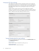
Conventions The following conventions are used in this guide. Management tool This guide uses specific syntax when directing you to interact with the management tool user interface. See the following image for identification of key user-interface elements and the table below for example directions: Main Sub-menu Example directions in this guide What to do in the user interface Select Wireless > Radio. Click Wireless on the main menu, and then click Radio on the sub-menu. Set Mode to 5 GHz IEEE 802.11n.
A Resetting to factory defaults Factory reset procedures To force the HP 501 into its factory default state, follow the procedures in this section. Caution Resetting the HP 501 to factory defaults deletes all configuration settings, resets the manager user name and password to admin, and enables the DHCP client on the Ethernet port. If no DHCP server assigns an address to the HP 501, its address defaults to 192.168.1.1.