
HP 517 802.11ac Unified Walljack Configuration Guide v6.4.0
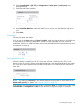

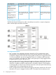
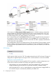

VLAN=20. Port 3 and Port 4 are both on the same Uplink VLAN allowing untagged traffic to
be exchanged between the ports.
NOTE:
• Port 5 is not shown in this diagram. It is an unmanaged port. Traffic on Port 5 is hard-wired
to the Pass Through port and is not handled by the switch.
• The punch-down block is not shown in this diagram. It provides the same type of connection
as the Uplink port. Only one port can be used at a time.
Dynamic VLAN configuration examples
The examples in this section illustrate how dynamic VLANs are applied in different scenarios: when
not binding to a VSC, and when binding to access-controlled and non-access-controlled VSCs.
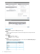
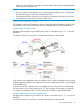
Example 1. When not binding to a VSC
If deploying this example using an MSM720, the switch is connected to port 1, 2, 3, or 4 on the
MSM720.
On all other controllers, the switch is connected to the LAN port on the controller.
In this scenario, the authentication option is enabled on Port 2, with the credentials for user A being
validated against the RADIUS server attached to the switch. Authentication traffic is sent untagged
to the RADIUS server.
A dynamic VLAN (30) is defined in the user's RADIUS account. Once the user is authenticated,
the user's traffic is sent on VLAN 30 by the HP 517. In this scenario, the controller is used purely
to configure and manage the HP 517. It does not handle user traffic or authentication traffic.
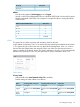
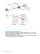
Example 2. When binding to a non-access-controlled VSC
If deploying this example using an MSM720, the switch is connected to port 1 ,2, 3, or 4 on the
MSM720.
On all other controllers, the switch is connected to the LAN port on the controller.
Port configuration page 27