HP 517 Unified Walljack Installation Guide Abstract This document describes the procedure to install and initially configure the HP 517 Unified Walljack (HP 517). It is intended for professional installers who are trained in RF installation and knowledgeable in local regulations including building and wiring codes, safety, channel, power, indoor/outdoor restrictions, and license requirements for the country of use.
© Copyright 2014 Hewlett-Packard Development Company, L.P. The information contained herein is subject to change without notice. The only warranties for HP products and services are set forth in the express warranty statements accompanying such products and services. Nothing herein should be construed as constituting an additional warranty. HP shall not be liable for technical or editorial errors or omissions contained herein. Acknowledgments Microsoft® is a U.S.
Contents 1 Getting started...........................................................................................4 Overview................................................................................................................................4 Ports.......................................................................................................................................4 Radio and antennas...............................................................................................
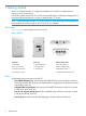
1 Getting started The HP 517 Unified Walljack is a single-radio dual-band 3x3:3 802.11ac walljack that can support up to 50 wireless clients. In its factory default state, the HP 517 can be provisioned through its web-based management tool using Microsoft Internet Explorer 8 or later, or Mozilla Firefox 17 or later. NOTE: When operating, the HP 517 is warm to the touch. When operating at room temperature, the face of the unit can be as high as 40°C (104°F). This is expected.
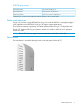
PoE PSE port power 802.3af powered No power out PSE port 4 802.3at powered Class 2 power via PSE port 41 Local DC powered Class 2 or 3 power via PSE port 4 1 Because up to 11 watts can be supplied, the software supports a class 3 override option. Radio and antennas The HP 517 provides a single IEEE 802.11a/b/g/n/ac radio for 802.11ac very-high throughput (VHT) applications and IEEE 802.11a/b/g/n for legacy support applications.
2 Installing the HP 517 The HP 517 is designed to be mounted on a standard NEMA-WD6 (US) or BS 4662 (International) electrical outlet box. If you use the optional HP Unified Wired-WLAN Walljack Table/Flush Wall Mount Kit (JL022A), the HP 517 can be mounted on a desktop or wall. The end user is responsible for ensuring that installation and use comply with local safety and radio regulations. IMPORTANT: This device requires professional installation.
Remove product from packaging Inspect the package contents and verify that they are free from defects. The package contains: • HP 517 Unified Walljack • Mounting bracket • Ethernet jumper cable • Screws • Documentation Installing on an electrical box Before you begin, run the required network cables through the bottom of the electrical outlet box on which you are installing the HP 517. Be sure to provide enough cable length to reach the HP 517.
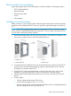
Installing on a wall When installing the HP 517 on a wall, ensure that the surface to which you attach the HP 517 and the fasteners you use can support at least 0.9 kg (2 lbs). Allow extra weight for cables. 1. Hold the optional Unified Wired WLAN Walljack Table/Flush Wall Mount panel in a vertical orientation against the wall where it will be installed. Mark two holes for the screws or user-supplied wall anchors. 2. If using wall anchors, drill two holes, typically 4.
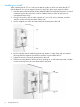
7. Connect the network cable from the panel to the RJ-45 Uplink port on the back of the HP 517. If required, also connect the cable providing support for pass-through devices to the Pass Through port on the back of the HP 517. 8. Push the HP 517 onto the mounting bracket on the box, then slide it down until it is fully engaged. Do not let go of the HP 517 until you confirm that it is securely in place. 9.
6. Connect the network cable from the panel to the RJ-45 Uplink port on the back of the HP 517. If required, also connect the cable providing support for pass-through devices to the Pass Through port on the back of the HP 517. 7. 8. 9. Push the HP 517 onto the mounting bracket, then slide it down until it is fully engaged. Do not let go of the HP 517 until you confirm that it is securely in place.
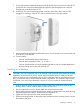
2. Connect the cables and power on the HP 517. IMPORTANT: When using the PoE PSE Ethernet LAN port 4 to power a 802.3af powered device (PD), the cable length from LAN port 4 to the PD must be no more than 3 m. a. Connect the cables: • If using a PoE switch, use an Ethernet cable to connect an unused factory-default PoE switch port to the HP 517 Uplink port.
3 LEDs Table 1 Startup behavior Power LED Uplink LED Radio LED Description Off Off Off The HP 517 has no power. Amber — — Power is applied. If the power LED remains amber for several minutes, the software has failed to load. If this occurs, reset or power cycle the HP 517. If this condition persists, contact HP support. Flashing green — — Flashing every two seconds: The HP 517 is starting up.
Table 2 Controlled behavior (continued) LED State Green Flashing green Description Class 3 power is being supplied to the device attached to port 4. A fault condition while a Class 3 PoE device is configured on port 4.
4 Support and other resources Contacting HP For worldwide technical support information, see the HP support website: http://www.hp.com/support Before contacting HP, collect the following information: • Product model names and numbers • Technical support registration number (if applicable) • Product serial numbers • Error messages • Operating system type and revision level • Detailed questions Related information The following documents provide related information: • HP 517 802.
Table 3 Document conventions (continued) Convention Element Monospace text • File and directory names • System output • Code • Commands, their arguments, and argument values Monospace, italic text • Code variables • Command variables Monospace, bold text WARNING! CAUTION: IMPORTANT: NOTE: Emphasized monospace text Indicates that failure to follow directions could result in bodily harm or death. Indicates that failure to follow directions could result in damage to equipment or data.
5 Documentation feedback HP is committed to providing documentation that meets your needs. To help us improve the documentation, send any errors, suggestions, or comments to Documentation Feedback (docsfeedback@hp.com). Include the document title and part number, version number, or the URL when submitting your feedback.
A Regulatory information For important safety, environmental, and regulatory information, see Safety and Compliance Information for Server, Storage, Power, Networking, and Rack Products, available at http:// www.hp.com/support/Safety-Compliance-EnterpriseProducts.