HP 517 802.11ac Unified Walljack Configuration Guide Abstract This document describes how to install and initially configure the HP 517 models J9841A (AM), J9842A (WW), J9843A (JP), J9844A (IL). These products are hereafter referred to as HP 517.
© Copyright 2014 Hewlett-Packard Development Company, L.P. The information contained herein is subject to change without notice. The only warranties for HP products and services are set forth in the express warranty statements accompanying such products and services. Nothing herein should be construed as constituting an additional warranty. HP shall not be liable for technical or editorial errors or omissions contained herein. Acknowledgments Microsoft® and Windows®, are U.S.
Contents 1 Introduction...............................................................................................4 Configuration...........................................................................................................................4 Configuration considerations......................................................................................................4 2 Provisioning the HP 517...............................................................................
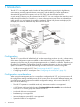
1 Introduction The HP 517 is an integrated switch/wireless AP designed from the ground-up for high-density environments, providing optimal Internet connectivity, and the delivery of other applications demanded by guests and occupants, such as IPTV, VoIP, and other IP-based services. A wide variety of devices can be connected to the HP 517.
• Ekahau is not supported. • Severe interference detection/mitigation, including spectral analysis, is not supported. • Load balancing is not supported. • Airtime fairness is not supported. • Tx beamforming is not supported. • Aeroscout tags are not supported. • Tx protection is not configurable, but is automatically supported using a combination of RTS/CTS and CTS-to-self. • Guard interval is not configurable, but is always set to Short.
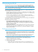
2 Provisioning the HP 517 Provisioning is the means by which you change the factory default IP addressing method and controller discovery settings on the HP 517. These settings apply to the HP 517 Uplink port only. NOTE: Provisioning settings are retained when the HP 517 is restarted or power cycled, but are removed when the HP 517 is reset to factory defaults. Provisioning is generally not required when deploying the HP 517 in simple (unrouted layer 2) network topologies.
computer to the switch and connect another Ethernet cable from a PoE port on the switch to the Uplink port on the HP 517. 4. 5. 6. 7. 8. • If using a PoE injector, first ensure that it is powered off. Then, connect an Ethernet cable from your computer to the data in port of the PoE injector and connect another Ethernet cable from the data and power out port on the injector to the Uplink port on the HP 517. • If using an HP AC/DC Power Adapter (JD055B), connect it to the power connector on the HP 517.
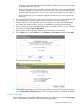
Settings Interface Specify the VLAN ID that will be used on the Uplink port for management traffic. This VLAN is only used for the discovery of a controller and does not apply to user traffic sent on Ports 1 to 4 or the Uplink port. To apply a VLAN to a port for user traffic, see “VLAN” (page 23). Assign IP address via Select how the HP 517 will obtain an IP address for the Uplink port. DHCP client Enable this option to have the Uplink port act as a DHCP client and request an IP address from a DHCP server.
In this type of environment. deployment can be a challenge, since the HP 517 must already be configured with the correct 802.1X username and password before it is connected to the secured switch port. There are three solutions to this problem: • During HP 517 deployment, 802.1X is deactivated on the secured switch port. The HP 517 is connected and provisioned with the correct 802.1X settings by the controller. Once the HP 517 is synchronized, 802.
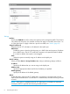
Settings Discover using DNS When this option is enabled, the HP 517 attempts to connect with a controller using the host names in the order that they appear in the list. The HP 517 appends each host name with the specified Domain name. For example, the screen image above shows the HP 517 configured to search using the following names: • controller-1.mydomain.com • controller-2.mydomain.com If you define a name that contains a dot, then the domain name is not appended.
Once the HP 517 is synchronized with a controller, location information is displayed by selecting Controlled APs >> Overview > Discovered APs and then selecting an AP in the table to open the AP details page.
3 Configuring the switch ports This chapter explains how to configure the switch ports using the management tool on a controller. This section assumes that you are familiar with the operation of the MSM7xx management tool. If not, see the MSM7xx Controllers Configuration Guide. NOTE: Wired devices connected to the switch ports cannot communicate with wireless devices connected to the same HP 517.
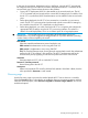
nl • If you select Controller > Controlled APs > [group] > [access-device] >> Configuration > Switch ports, you see the following page: nl Table description Inherited (title bar) Only appears at the Group or AP level. To define configuration settings for the switch ports you must first clear the global Inherited checkbox, or the individual checkbox available for each port.
Inherited (column) Use these check boxes to enable inheritance on a per-port basis. Port configuration page Ports 1 to 4 each have their own configuration page. The following screen shows the configuration page for Port 4. Configuration settings for the other ports are identical, except for the Power over Ethernet option which is only available on Port 4. nl Each configuration option on this page is discussed in detail in the sections that follow.
Settings Port settings Port name Friendly name assigned to the port. Flow control When this option is enabled, the HP 517 uses Ethernet flow control when exchanging traffic with a connected device. If you are using the Rate limiting option to limit ingress traffic you should enable flow control. This will ensure that a client device does not send traffic in excess of the ingress limit (providing that the client device supports flow control).
The PoE LED on the front on the HP 517 provides visual feedback on the status of the power forwarding on port 4 as follows: • Off: No PoE device is connected. • Amber: On indicates that Class 1 or 2 power is being supplied to the device attached to port 4. Blinking indicates a fault condition while Class 1 or 2 PoE is configured on port 4. • Green: On indicates that Class 3 power is being supplied to the device attached to port 4.
Four egress traffic queues are defined on the Uplink port. In order of priority, the queues are: Queue Priority setting 1 Very-high 2 High 3 Normal 4 Low NOTE: These queues are also used by traffic from the wireless network. To see how QoS is implemented for wireless traffic, see the MSM7xx Controllers Configuration Guide. Default traffic priority (Not available when Send Network Policy TLV is enabled.
Priority lookup option QoS marking on incoming traffic Queue to which traffic Is a VLAN defined on QoS marking on traffic is assigned the port? exiting the Uplink port 802.1p 802.1p + DiffServ Queue defined by 802.1p Priority lookup. Yes 802.1p marking is preserved. No Unmarked. 802.1p marking is removed. Queue defined by the 802.1p and then DiffServ Priority lookup. Yes Both 802.1p and DiffServ markings are preserved. No DiffServ marking is preserved.
This DiffServ mechanism classifies traffic based on the value of the Differentiated Services (DS) codepoint field in IPv4 and IPv6 packet headers (as defined in RFC2474). The codepoint is composed of the six most significant bits of the DS field. Queue DiffServ codepoint (DSCP) value 1 48 - 63 2 32 - 47 3 24 - 31 4 8 - 23 Queue defined by the Default traffic priority setting or the LLDP Network Policy TLV if defined. (See LLDP Network Policy TLV QoS setting for details.
2. Select Controller >> Security > MAC lists. 3. Select Add New MAC List. The Add/Edit MAC list page opens. Each entry in the MAC list contains a MAC address and its associated mask. 4. 5. 6. For Name, specify a name to identify the MAC address list. For MAC address, specify the MAC address to match. Define the address using 12 hexadecimal numbers in the format nn:nn:nn:nn:nn:nn. For Mask, specify the mask that will be applied to the MAC address. This is a binary mask in the format nn:nn:nn:nn:nn:nn.
10. Select Controlled APs > [HP 517] >> Configuration > Switch ports > [switch-port] in the management tool. 11. Select the MAC filter checkbox. 12. Under Available MAC lists, select each MAC list you want to use and select the right arrow icon. 13. Select Save. Link settings Sets the port speed and duplex. If you do not use the Auto setting for Speed or Duplex, make sure that the device to which the port is connected has a matching configuration.
Application type profiles Application type This release only supports the Voice application type VLAN ID Specify a VLAN ID for this profile. This VLAN will be assigned to the switch port when the profile is used. VLAN tagging • Tagged: The VLAN is tagged. • Untagged: The VLAN is untagged. L2 priority Select the layer 2 priority setting. This setting is used instead of the Default traffic priority set for the switch port.
L2 priority QoS queue Very high - 7 nl DiffServ This value only applies if VLAN tagging is set to Tagged. Specify a value for the Differentiated Services codepoint (DSCP) field in IPv4 and IPv6 packet headers (as defined in RFC2474). The codepoint is composed of the six most-significant bits of the DS field. DiffServ codepoint (DSCP) value QoS queue > 33 1 26 - 33 2 18 - 25 3 1 - 17 4 0 Disabled VLAN This option lets you define a primary and secondary VLAN on the port.
This table only applies when the following options are disabled: • Quarantine VLAN • Allow dynamic VLAN assignment Notes on Uplink tagging When the Uplink tagging option is selected, incoming and outgoing traffic on ports 1 to 4 is untagged. Internally however, the traffic is tagged with the Primary VLAN ID. This means that if two ports are set to Uplink tagging with different Primary VLAN IDs, then traffic cannot be exchanged between the two ports.
When this option is disabled: • If the port is bound to an access-controlled VSC, the dynamically assigned VLAN is applied on the controller and not on the HP 517. The dynamic VLAN will override the VLAN settings on the VSC egress mapping on the controller. See “Example 4. Dynamic VLAN usage when Allow dynamic VLAN assignment is disabled” (page 29). Dynamic VLANs can be assigned using the following methods, which are described in detail in the MSM7xx Controllers Configuration Guide.
Port configuration Incoming traffic on the port Outgoing traffic on the port Uplink port Primary VLAN=Uplink tagging Primary VLAN ID=20 Only untagged traffic is accepted. Untagged. Tagged with the user's dynamically assigned VLAN. Allow dynamic VLAN assignment=On Primary VLAN=Uplink tagging Primary VLAN ID=20 Only untagged traffic and Untagged or tagged with traffic tagged with VLAN 40 VLAN 40. is accepted. Tagged with VLAN 40 or the user's dynamically assigned VLAN.
VLAN=20. Port 3 and Port 4 are both on the same Uplink VLAN allowing untagged traffic to be exchanged between the ports. NOTE: • Port 5 is not shown in this diagram. It is an unmanaged port. Traffic on Port 5 is hard-wired to the Pass Through port and is not handled by the switch. • The punch-down block is not shown in this diagram. It provides the same type of connection as the Uplink port. Only one port can be used at a time.
In this scenario, Port 2 is bound to a non-access-controlled VSC named Guest. This VSC is configured to provide 802.1X authentication with the login credentials for user A validated against the local user list stored on the controller. A local account is created for user A with an egress VLAN ID of 30. Once user A is authenticated, the user's traffic is sent on VLAN 30. Example 3.
In this scenario, Port 2 is bound to an access-controlled VSC named Guest. Since the Guest VSC is not the default VSC, a VLAN definition (10) must be assigned to the VSC to ensure that user traffic is properly routed from the HP 517 to the VSC on the MSM7xx. 802.1X authentication is enabled on this VSC with credentials being validated against the local user accounts on the controller. A local account is created for the user, with an egress VLAN ID of 10.
In this scenario, the Allow dynamic VLAN assignment option is disabled. However, dynamically assigned VLANs can still be used by binding the port to an access-controlled VSC. In this case, the dynamically assigned VLAN is applied on the controller and not on the HP 517. It overrides the VLAN settings on the VSC egress mapping on the controller. Port 2 is bound to the VSC named Guest. Authentication occurs using the local user accounts on the controller (via 802.1X or HTML-based logins).
The following examples illustrate various ways of binding to an access-controlled VSC. Example 1. Binding to the default VSC If deploying this scenario using an MSM720, the switch is connected to port 1, 2, 3, or 4 on the MSM720, and the MSM720 is connected to the private network using port 5 or 6. On all other controllers, the switch is connected to the LAN port on the controller, and the controller is connected to the private network using the Internet port.
Key configuration settings for the VSC are as follows: Example 2. Binding to a specific VSC If deploying this scenario using an MSM720, the switch is connected to port 1, 2, 3, or 4 on the controller, and the MSM720 is connected to the private network using port 5 or 6. Also, any use of VLAN 10 should be replaced with VLAN 11. On all other controllers, the switch is connected to the LAN port on the controller, and the controller is connected to the private network using the Internet port.
must be assigned to the controller port to ensure that user traffic is properly routed from the HP 517 to the VSC on the controller. Key configuration settings for Port 2 are as follows: Configuration of the VLAN on the controller is done by defining a network profile with VLAN 10 and binding it to the LAN port on the controller. Define the new network profile on the Controller >> Network > Network profiles page and assign VLAN 10 to it.
Key configuration settings for the VSC are as follows: Example 3. Binding to multiple VSCs If deploying this scenario using an MSM720, the switch is connected to port 1, 2, 3, or 4 on the MSM720, and the MSM720 is connected to the private network using port 5 or 6. Also, any use of VLAN 10 should be replaced with VLAN 11. On all other controllers, the switch is connected to the LAN port on the controller, and the controller is connected to the private network via the Internet port.
In-room equipment An in-room mini-bar is connected to Port 1, which is bound to the VSC named Equipment. Authentication occurs using the mini-bar MAC address via the local user accounts on the controller. Since the Equipment VSC is not the default VSC, a VLAN definition must be assigned to the port to ensure that traffic is properly routed from the HP 517 to the Equipment VSC on the controller.
Key configuration settings for the VSC are as follows: User A Wired guests, as illustrated by user A, connect to Port 2, which is bound to the VSC named Guest. Authentication occurs via HTML, using the local user accounts on the controller. Once authenticated, user A gains access to resources on the private network according to the configuration of the public access interface feature on the controller.
Because the VLAN is only used to route traffic to the appropriate VSC on the controller, it does not require an IP address. Key configuration settings for the VSC are as follows: User B Wireless guests, illustrated by user B, connect to the HP 517 radio using the SSID Guest. This SSID is defined in the VSC named Guest which is bound to the HP 517 using Controlled APs > [group] >> VSC bindings on the controller. (There is no option on the HP 517 to bind a VSC to the wireless port.
Binding to a non-access-controlled VSC When a port is bound to a non-access-controlled VSC, the controller is used for authentication tasks only. Authentication can occur by checking the user's MAC address or via 802.1X. Access control must then be performed by another device on the network, or not at all. Example 1. Binding to a specific VSC If deploying this scenario using an MSM720, the switch is connected to port 1, 2, 3, or 4 on the MSM720.
option. Authentication occurs via the local user accounts on the controller (via 802.1X or MAC-based). Once authenticated, user A gains direct access to any resources on the private network. Key configuration settings for Port 2 are as follows: Key configuration settings for the VSC are as follows: If the private network is operating on a VLAN, you can assign a VLAN to Port 2. In the following scenario, once authenticated, the user gains direct access to any resources on the private network using VLAN 10.
Authentication This option is only available if the VSC binding option is not enabled. Authentication can be enabled on Ports 1 to 4, allowing access to the ports to be controlled using the MAC address of a client station or via 802.1X. If a client station fails to authenticate, access to the port is blocked unless the Quarantine VLAN option (under VLAN) is enabled, in which case access is enabled but all traffic is forced onto the specified quarantine VLAN.
802.1X This option enables support for client stations with 802.1X client software that uses EAP-TLS, EAP-TTLS, EAP-SIM, PEAP, or any other transparent EAP method. Encryption is not supported. 802.1X logins are authenticated via an external RADIUS server defined by the RADIUS profile selected for RADIUS. MAC-based This option lets you control access based on a client station's MAC address. Addresses are authenticated via an external RADIUS server defined by the RADIUS profile selected for RADIUS.
4 Viewing status information The MSM7xx management tool provides a number of pages where you can view HP 517 status information. Dashboard The dashboard provides a wide variety of information about the operation of the wireless network. This section presents some of the pages you can use to view information about the HP 517. For a description of all dashboard pages, see the MSM7xx Controllers Configuration Guide.
Access Points per Bandwidth Utilization - Current Displays the number of APs currently operating in each bandwidth utilization range: <50%, 50% -80%, >80%. Only online access points with radios that are enabled and operating in access point and/or local mesh mode are shown on this chart. The percent utilization is calculated by comparing the total throughput (transmitted/received) of all radios on an AP for the last minute against the maximum throughput that the radios could theoretically achieve.
Most Active Wireless Clients - Last 24 Hours Displays the ten most active wireless clients during the last 24 hours based on the total amount of traffic (in bytes) sent and received. If the name of the wireless client is not known, then its MAC address is displayed. Hover your mouse pointer over the name to display the total time that the client has been connected and its average throughput.
Access point list Status • Green: The controller is synchronized. • Red: The controller is not functioning normally. See the Diagnostic column for details. • Grey blinking: An action is pending for this controller. See the Action column for details. AP name Name assigned to the AP. By default, this is the AP serial number. Serial number Serial number assigned to the AP. Wireless services Indicates the status of wireless services on the AP. A separate icon appears for each radio on the AP.
Wireless clients Indicates the number of wireless clients currently associated with the AP. Click the number to see more information on associated clients. Diagnostic Indicates the status of the AP with regards to management by the controller. Diagnostic Description AP limit exceeded The maximum number of APs are already being managed by the controller as defined on the Controller >> Status > AP limits page. Detected The AP was detected by the controller.
Diagnostic Description Synchronized The AP is up and running, offers wireless services, and had its firmware and configuration settings successfully updated by the controller. Synchronized/License violation Although the AP is synchronized it is non-functional (quarantined) due to a license violation. You must change the configuration to omit the affected licensed feature or acquire and install a valid license.
Access point location Location information assigned when the AP was defined. Access point contact Contact information assigned when the AP was defined. Group name Group to which the AP is assigned. Networking information - AP Control channel Interface the AP is using to communicate with the controller. VLAN identifier VLAN the AP is using to communicate with the controller. MAC address AP MAC address. IP address AP IP address. IP netmask Network mask associated with the IP address.
Wireless information MAC address MAC address of the wireless interface. Operating mode Mode the AP is currently operating in. Possible values are: • AP only: Only provides access point functionality, local mesh links cannot be created. • Monitor: Disables access point and local mesh functions. Use this option for continuous scanning across all channels in all supported wireless modes. This mode also enables 802.11 traffic to be traced using the Controller >> Tools > Network trace feature.
AP name Name of the AP with which the client station is associated. Radio Radio on the AP that the client station is using. MAC Address MAC address of the client station. IP address IP address assigned to the client station. Username Name with which the user logged in. SSID SSID assigned to the client station. Security Indicates if the client station has been authorized. Duration Indicates how long the client station has been authorized.
Port Indicates the port name and status. • Green light: Port is active. • Red light: Port is not active. Receive • Frames: Number of frames received. • Dropped: Number of received frames that were dropped. • Errors: Number of frames received with errors. This can be caused by overruns, unaligned frames, bad CRCs, frame length violations, or late collisions. Transmit • Frames: Number of frames transmitted. • Dropped: Number of transmitted frames that were dropped.
Bridge port statistics To see the traffic forwarding tables for the bridge and the switch ports, select the HP 517 in the Network Tree under Controlled APs, then in the right pane select Status > Bridge. For example: nl Bridge status State Current state of the bridge. • Listening: Initial state. Port is not forwarding packets but listens for other bridges. • Learning: Bridge learns about other bridges on that port. Port is not forwarding packets. • Forwarding: Port is forwarding packets.
Spanning Tree Protocol For complete definitions of these fields refer to the following document, which is available in a number of locations on the Internet. • ANSI/IEEE Std 802.1D, 1998 Edition - Part 3: Media Access Control (MAC) Bridges Bridge forwarding table This table lists the forwarding entries learned by the bridge. Port Identifies the port on the HP 517 on which traffic is forwarded. The interface number corresponds to the last digit of the port ID in the Bridge status box.
5 Support and other resources Online documentation You can download documentation from the HP Support Center website at: www.hp.com/support/ manuals. Search by product number or name. Contacting HP For worldwide technical support information, see the HP Support Center website: www.hp.