
HP Power over Ethernet (PoE/PoE+) Planning and Implementation Guide

14-5
Planning and Implementation for the HP 5400R zl2 Switches
Introduction
■ Full redundancy. Half of the totally available PoE power can be allocated
and half is held in reserve for redundancy. This mode is allowed only for
even number of power supplies.
■ N+1. One of the power supplies is held in reserve for redundancy. If a
single power supply fails, no powered devices are shut down. If power
supplies with different ratings are used, the highest-rated power supply is
held in reserve to ensure full redundancy. This mode is allowed for both
even/odd number of power supplies.
■ Redundancy(N+1/Full) only with like power supplies.
■ Redundancy is not allowed for AUX faulted J9830A power supplies.
Note When changing from one method to another, always check the current level
of PoE usage before implementing the change. The change could cause
existing connection to lose PoE power.
When considering redundant power, also consider the power source for the
power supplies. Each power supply should be connected to a separate power
source circuit in order to supply complete redundancy. Should one circuit fail,
it would then be possible for the other circuit to continue supplying power to
the second power supply in the switch, keeping the switch running.
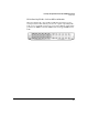
HP PoE and PoE+ zl Modules
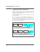
HP 24-Port Gig-T PoE+ v2 zl Module
HP 24-Port Gig-T PoE+ v2 zl Module (J9534A) has 24 auto-sensing 10/100/1000
Base-T RJ-45 ports that are capable of providing PoE/PoE+ power. All ports
have the IEEE 802.3ab Auto-MDIX feature and support IEEE 802.3at PoE+.