
HP Power over Ethernet (PoE/PoE+) Planning and Implementation Guide


5-4
Planning and Implementation for the HP 2610-PoE Switches
Planning the PoE Configuration
Planning the PoE Configuration
This section assists you in building a reliable and, if required, redundant PoE
configuration. Using the following examples you can plan, build, and connect
your PoE devices quickly and easily.
Your configuration may vary however this section discusses some of the more
common configurations.
There are three configurations:
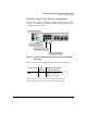
■ HP 2610-24-PPoE Switch
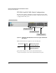
■ HP 2610-24-PoE Switch
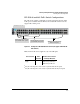
■ HP 2610-48-PoE Switch
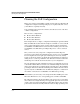
Each example shows a complete configuration including an optional 600 RPS/
EPS or 610 EPS unit. A table shows the PoE power available to connected PoE
devices when using just the switch or when using the switch and either the
600 RPS/EPS or 610 EPS unit. The tables show the available power when the
600 RPS/EPS or 610 EPS unit is providing PoE power to connected switch
devices.
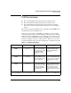
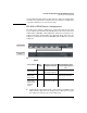
Once you have selected your specific configuration and the PoE power
provided, you then add up the maximum amount of power each of your IEEE
802.3af-compliant devices require (use maximum power in watts, usually
found on a product’s data sheet). Adjust this total maximum power figure by
adding 16% to account for possible line loss. This value must be less than the
maximum power available shown in the table for your configuration.
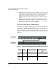
If you are planning to include redundant power in your configuration you need
to determine which PoE devices must receive redundant PoE power, then total
their power requirements as explained in the paragraph above. The maximum
power figure must be less than the maximum power available when the switch
is powered by the 600 RPS/EPS or the 610 EPS unit, taking into consideration
the number of switches the 600 RPS/EPS or 610 EPS unit is powering.
Note Full redundancy is achieved by connecting both the RPS and EPS ports of the
HP 2610-PoE Switches to the corresponding ports of an HP 600 RPS/EPS.
The following examples only show the EPS connections, however, remember
these switches use a single internal power supply which provides two isolated
output voltages for switch and PoE functionality. One supply voltage provides
power for the switch functionality while the isolated voltage provides power