
HP Power over Ethernet (PoE/PoE+) Planning and Implementation Guide


10-8
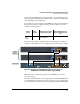
Planning and Implementation for the HP 3500-PoE Switches
Planning the PoE Configuration
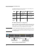
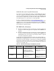
The table in this example configuration shows the PoE power available for
the HP 3500-48-PoE Switch.
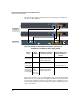
Figure 10-4. Example of two HP 3500-48-PoE Switches connecting to an
HP 620 External and Redundant Power Supply (J8696A)
Each of the switches can receive full redundant power from the HP 620 RPS/
EPS should one of the internal power supplies fail. The lowest loaded bank of
ports (1-24 or 25-48) has 22 watts reserved. That power is available for use by
the two highest priority ports in the bank, (in a default configuration ports 1
and 2, or 25 and 26).
HP 3500 48-port
switches
HP 620 RPS/EPS
Source of
Power
Watts
Available
Number of Ports Powered
and Average watts/Port
Redundant Number of Ports
Powered and Average
watts/Port
Internal PoE
Power Supply
398 25 @ average 15.4 W each
48 @ average 7.5 W each
48 @ average 4.0 W each
None
Internal plus
External PoE
power Supply
398 + 388 48 @ average 15.4 W each 24 @ average 15.4 W each
48 @ average 7.5 W each
External PoE
Power Supply
(failed Internal
Power Supply)
388
(22 W is
reserved for
either ports
1-24 or 25-48)
25 @ average 15.4 W each
48 @ average 7.5 W each
48 @ average 4.0 W each
None