
Advanced Traffic Management Guide K/KA/KB.15.15
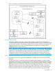


Types of Multiple Spanning Tree Instances
A multiple spanning tree network comprises separate spanning tree instances existing in an MST
region. (There can be multiple regions in a network.) Each instance defines a single forwarding
topology for an exclusive set of VLANs. By contrast, an STP or RSTP network has only one spanning
tree instance for the entire network, and includes all VLANs in the network. (An STP or RSTP network
operates as a single-instance network.) A region can include two types of STP instances:
• Internal spanning tree Instance (IST Instance)
This is the default spanning tree instance in any MST region. It provides the root switch for
the region and comprises all VLANs configured on the switches in the region that are not
specifically assigned to Multiple Spanning Tree Instances (MSTIs, described below).
Within a region, the IST instance provides a loop-free forwarding path for all VLANs associated
with it. VLANs that are not associated with an MSTI are, by default, associated with the IST
instance. Note that the switch automatically places dynamic VLANs (resulting from GVRP
operation) in the IST instance. Dynamic VLANs cannot exist in an MSTI (described below).
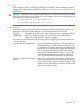
• Multiple Spanning Tree Instance (MSTI)
This type of configurable spanning tree instance comprises all static VLANs you specifically
assign to it, and must include at least one VLAN. The VLANs you assign to an MSTI must
initially exist in the IST instance of the same MST region. When you assign a static VLAN to
an MSTI, the switch removes the VLAN from the IST instance. (Thus, you can assign a VLAN
to only one MSTI in a given region.) All VLANs in an MSTI operate as part of the same single
spanning tree topology. (The switch does not allow dynamic VLANs in an MSTI.)
CAUTION: When you enable MSTP on the switch, the default MSTP spanning tree configuration
settings comply with the values recommended in the IEEE 802.1s Multiple Spanning Tree Protocol
(MSTP) standard. Inappropriate changes to these settings can result in severely degraded network
performance. For this reason, HP strongly recommends that changing these default settings be
reserved only for experienced network administrators who have a strong understanding of the IEEE
802.1D/w/s standards and operation.
Operating rules
• All switches in a region must be configured with the same set of VLANs, as well as the same
MST configuration name and MST configuration number.
• Within a region, a VLAN can be allocated to either a single MSTI or to the region's IST
instance.
• All switches in a region must have the same VID-to-MST instance assignment.
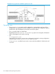
• There is one root MST switch per configured MST instance.
• Because boundary ports provide the VLAN connectivity between regions, all boundary ports
on a region's root switch should be configured as members of all static VLANs defined in the
region.
• There is one root switch for the Common and Internal Spanning Tree (CIST). At any given
time, all switches in the network will use the per-port hello-time parameter assignments
configured on the CIST root switch.
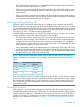
• Where multiple MST regions exist in a network, there is only one active, physical communication
path between any two regions, or between an MST region and an STP or RSTP switch. MSTP
blocks any other physical paths as long as the currently active path remains in service.
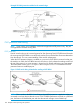
• Within a network, an MST region appears as a virtual RSTP bridge to other spanning tree
entities (other MST regions, and any switches running 802.1D or 802.1w spanning tree
protocols).
About MSTP 125