
Advanced Traffic Management Guide K/KA/KB.15.15

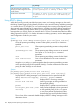
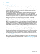
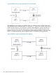
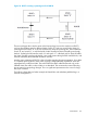
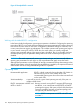
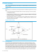


Figure 22 RSTP forming a single spanning tree across all VLANs
The topology has four switches running RSTP. Switch “A” is the root switch. In order to prevent a
loop, RSTP blocks the link between switch “B” and switch “D”. There are two VLANs in this network
(VLAN 10 and VLAN 20). Since RSTP does not have VLAN intelligence, it forces all VLANs in a
layer 2 domain to follow the same spanning tree. There will not be any traffic through the link
between switch “B” and switch “D” and hence the link bandwidth gets wasted. On the other hand,
RPVST+ runs different spanning trees for different VLANs. Consider the following diagrams.
Figure 23 RPVST+ creating a spanning tree for VLAN 10
164 Rapid per-VLAN spanning tree (RPVST+) operation