
Advanced Traffic Management Guide K/KA/KB.15.15

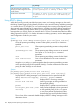
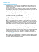
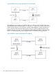
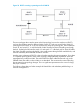
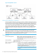
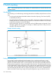


Figure 24 RPVST+ creating a spanning tree for VLAN 20
The two topologies above are the same as the first topology, but now the switches run RPVST+
and can span different trees for different VLANs. Switch “A” is the root switch for the VLAN 10
spanning tree and switch “D” is the root switch for the VLAN 20 spanning tree. The link between
switch “B” and switch “D” is only blocked for VLAN 10 traffic but VLAN 20 traffic goes through
that link. Similarly the link between switch “A” and switch “C” is blocked only for VLAN 20 traffic
but VLAN 10 traffic goes through that link. Here, traffic passes through all the available links, and
network availability and bandwidth utilization increase.
Another major advantage of RPVST+ is that it localizes topology change propagation. Since there
is a separate spanning tree for each VLAN, topology changes affecting a particular VLAN are
propagated only inside that VLAN. The switch flushes the MAC addresses learned only on the
affected VLAN, the traffic on other VLANs is not disturbed. This minimizes the network flooding
due to spanning tree topology changes. This is a significant improvement in the case of a large,
flat, layer 2 network.
The following figure shows a further example of shared links and redundant path-blocking in a
network running RPVST+.
About RPVST+ 165