
HP Power over Ethernet (PoE/PoE+) Planning and Implementation Guide


11-7
Planning and Implementation for the HP 3500-PoE yl Switches
Planning the PoE or PoE+ Configuration
sheet). Adjust this total maximum power figure by adding 16% to account for
possible line loss. This value must be less than the maximum power available
shown in the table for your configuration.
HP 3500-24G-PoE yl Switch Configuration
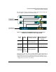
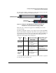
The table in this example configuration contains entries that show the PoE
power available for the HP 3500-24G-PoE yl Switch.
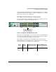
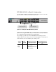
Figure 11-1. Example of an HP 3500-24G-PoE yl Switch
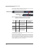
Note: If any of the mini-GBIC ports are used (21-24) the corresponding RJ-45
port will not be supplied with PoE power. Therefore that needs to be taken
into consideration when planning per port PoE wattage.
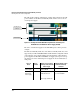
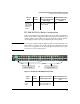
If for example, port 24 is used for a mini-GBIC, then the RJ45-port 24 is
disabled. Therefore the PoE power that was being supplied to the RJ45-port
24 is returned to the total available pool of PoE power.
All 24 ports can receive up to 15.4
watts of PoE power
Source of
Power
Watts
Available
Number of Ports Powered
and Average watts/Port
Redundant Number of Ports
Powered and Average watts/
Port
Internal PoE
Power
Supply
398 24 @ average 15.4 W each for
a total of 369.6 W
None