
HP Power over Ethernet (PoE/PoE+) Planning and Implementation Guide


11-8
Planning and Implementation for the HP 3500-PoE yl Switches
Planning the PoE or PoE+ Configuration
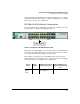
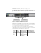
The table in this example configuration contains entries that show the PoE
power available for the HP 3500-24G-PoE yl Switch when connected to an
external power supply.
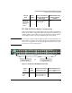
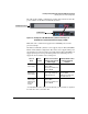
Figure 11-2. Example of two HP 3500-24G-PoE yl Switches connecting to an
HP 620 External and Redundant Power Supply (J8696A)
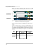
The same considerations apply for the mini-GBIC ports as in the previous
example.
Two HP 3500-24G-PoE yl Switches or two HP 3500-24-PoE yl Switches can be
supported by one HP 620 RPS/EPS. This is a full redundant configuration. Both
of the switches can be supplied with power should either of their internal
power supplies fail. The HP 620 RPS/EPS can supply system power to keep
the switch powered on and PoE power to supply the attached PoE devices
with power.
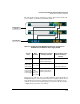
HP 3500yl 24 port
switches
HP 620 RPS/EPS
Source of
Power
Watts
Available
Number of Ports Powered
and Average watts/Port from
internal supply
Redundant Number of Ports
Powered and Average
watts/Port
Internal PoE
Power Supply
398 24 @ average 15.4 W each for
a total of 369.6 W
None
Internal plus
External PoE
Power Supply
398 + 388 24 @ average 15.4 W each
and 24 @ 7.5 W each
or
36 @ average 15.4 W each
24 @ average 15.4 W each
for a total of 369.6 W