
HP Power over Ethernet (PoE/PoE+) Planning and Implementation Guide


13-16
Planning and Implementation for the HP 5400zl/8200zl Switches
Planning the PoE Configuration
Planning the PoE Configuration
This section assists you in building a reliable and, if required, redundant PoE
configuration. Using the following examples you can plan, build, and connect
your PoE devices quickly and easily.
Your configuration may vary, however, this section discusses some of the more
common configurations.
Power Configuration for HP 5406zl/8206zl PoE
Switches
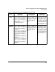
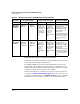
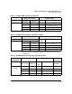
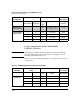
Tables 13-3 and 13-4 show the maximum system power available for various
power configurations. The configurations can be for full redundancy or for
N+1 redundancy, as illustrated in figure 13-1.
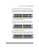
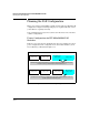
Figure 13-1. Example of Full and N+1 Redundancy Configuration
900 Watts PoE/
PoE+ power
900 Watts PoE/
PoE+ power
900 Watts PoE/
PoE+ power
900 Watts PoE/
PoE+ power
900 Watts PoE/
PoE+ power
900 Watts PoE/
PoE+ power
900 Watts PoE/
PoE+ power
900 Watts PoE/
PoE+ power
Full Redundancy: When full redundancy is configured, half of the available PoE/PoE+ power
is held in reserve to provide full replacement PoE/PoE+ power.
N+1: When N+1 redundancy is configured, one of the power supplies is held in reserve to
provide replacement PoE/PoE+ power.