
HP Power over Ethernet (PoE/PoE+) Planning and Implementation Guide


13-22
Planning and Implementation for the HP 5400zl/8200zl Switches
Configuration Examples
Configuration Examples
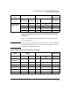
In the following configuration examples, each example shows a complete
configuration. A table shows the PoE power available to connected PoE
devices when using just the switch and when connecting an external power
supply.
Once you have selected your specific configuration and the PoE power
provided, you then add up the maximum amount of power each of your
devices require (use maximum power in watts, usually found on a product’s
data sheet). Adjust this total maximum power figure by adding 16% to account
for possible line loss. This value must be less than the maximum power
available shown in the table for your configuration.
(With External Power
Supplies Added>
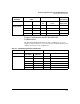
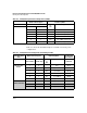
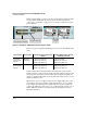
5 0 N+1 Up to 1200 W 1500 W
6 0 Full Up to 900 W 1800 W
0 5 N+1 Up to 3600 W 4500 W
0 6 Full Up to 2700 W 5400 W
Switch Model 5406zl/
8206zl
Number of Power Supplies
J9306A
Redundancy Model Non-Redundant
Power Available
@ 110 - 127 V @ 200-240 V N + 1 or
Full
Redundant PoE/PoE+
Power
Non-Redundant
PoE/PoE+ Power