
HP Power over Ethernet (PoE/PoE+) Planning and Implementation Guide


13-24
Planning and Implementation for the HP 5400zl/8200zl Switches
Configuration Examples
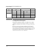
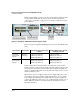
In this example (Figure 13-3) there are three modules in the chassis; 22 watts
is reserved for each module. In order to use the 22 watts, PDs must be
connected to each module, or all ports on one module could have the PoE
power disabled.
Figure 13-3. Example of a 5406zl with two power supplies, J8712A
There are two power supplies supplying 273 watts each for a maximum of 546
watts.
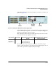
In this example the load must be balanced or split between two or three
modules in order to effectively use all 546 watts. The number of devices and
wattage must be split between the modules. This would also help limit the
effects of a single module failure. If one module fails, only the devices on that
module would lose power.
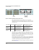
Alternatively, one power supply could be used to supply PoE power at 273
watts and the other power supply could be held in reserve as a secondary
power supply if the primary power supply fails. If both power supplies are
connected to different power sources, one could backup the other in case of
failure. With this option the user must manage the PoE usage in order to
maintain redundancy.
35 ports can receive up to
15.4 watts of PoE power
The PoE power for all ports on
this module has been disabled
Power Supply
J8712A
273 watts
for PoE
273 watts
for PoE
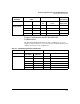
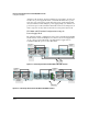
Source of Power Watts Available Number of Ports Powered and Average
watts/Port
Redundant Number of Ports Powered
and Average watts/Port
Two Internal
Power Supplies
(J8712A)
546 (without
redundancy)
35 @ average 15.4 W each
72 @ average 7.5 W each
136 @ average 4.0 W each
17 @ average 15.4 W
34 @ average 7.5 W each
68 @ average 4.0 W each
Two External
Power Supplies
(J8712A)
Additional 546 70 @ average 15.4 W each
144 @ average 7.5 W each
144 @ average 4.0 W each
35 @ average 15.4 W
72 @ average 7.5 W each
136 @ average 4.0 W each