
HP Power over Ethernet (PoE/PoE+) Planning and Implementation Guide


14-4
Planning and Implementation for the HP 5400R zl2 Switches
Introduction
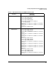
■ J9828A, which operates at 100-127 volts drawing a maximum of 8.5 amps,
or 200-240 volts drawing a maximum of 4.3 amps, and supplies 275 watts
of PoE/PoE+ power.
■ J9829A, which operates
at 110
-
127 volts drawing
a
maximum of 12
amps, or
200-240 volts drawing a maximum of 6.8 amps, and supplies 900 watts of
PoE/PoE+ power.
■ J9830A, which operates at 115-127
volts drawing
a
maximum of 15.5
amps,
or 200-240 volts drawing a maximum of 10 amps, and supplies 2500 watts
of PoE/PoE+ power.
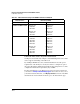
J9830A is a dual cord power supply with maximum total power of 2750 watts
and consists of the following:
■ MAIN line cord enables both outputs with rated power at PoE voltage -
1100 watts.
■ AUX line cord provides additional power at PoE voltage -1400 watts.
With a single power supply (J9830A) connected on both MAIN and AUX cords,
the POE power is 2500 watts but with MAIN only, the POE power is 1100 watts.
Note With AUX power alone, you cannot turn on the power supply while connecting
to a switch.
When considering redundant power, also consider the power source for the
power supplies. Each power supply should be connected to a separate power
source circuit in order to supply complete redundancy. Should one circuit fail,
it would then be possible for the other circuit to continue supplying power to
the second power supply in the switch, keeping the switch running.
Configuring PoE Redundancy
When considering redundant power, also consider the power source for the
power supplies. Each power supply should be connected to a separate power
source circuit in order to supply complete redundancy. Should one circuit fail,
it would then be possible for the other circuit to continue supplying power to
the second power supply in the switch, keeping the switch running.
When PoE redundancy is enabled, PoE redundancy occurs automatically. The
switch keeps track of power use and won’t supply PoE power to additional
PoE devices trying to connect if that results in the switch not having enough
power in reserve for redundancy if one of the power supplies should fail. The
redundancy methods are:
■ No PoE redundancy enforcement (default). All available power can be
allocated.