
HP Power over Ethernet (PoE/PoE+) Planning and Implementation Guide


14-21
Planning and Implementation for the HP 5400R zl2 Switches
Configuration Examples
fails, the J9828A can keep the switch running but cannot supply all the PoE
power that the J9829A was supplying. Therefore you need to plan very
carefully when using this configuration.
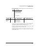
In a system with mixed power supplies, failover is calculated based on the
largest power supply failing. If it turns out to be the smaller power supply that
fails, some of the ports that were powered off during the power failure will
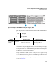
come back on. For example, in figure 14-6 there are mixed power supplies
offering 900 W+ 275 W for 1086([92.5 * (900+275)]W total. Failover power will
be calculated at 275 W, so if a power supply fails all the controllers will fall
back to a power level that can be supported by 275 W. If it turns out the 275
W supply failed, the system will detect that during the power supply polling
cycle and increase power back up to 900 W total. This would result in some
load coming back on if the total power used by all the loads in the box was
greater than 275 W.
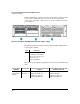
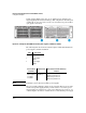
Example Configuration for HP 5406R zl2
With One PoE/PoE+ Power Supply
In this example there is one J9830A power supply operating at 115-127 volts,
providing 2500 watts for PoE/PoE+ usage.
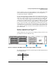
Figure 14-7. Example of an HP 5406R zl2 with One Power Supply (J9830A) @ 115-127 Volts
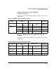
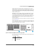
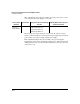
The following table shows the label and description for HP 5406R zl2 with one
power supply, J9830A:
Label Description
1 Front
2 Power Supply,
J9830A
3 Back