
HP Power over Ethernet (PoE/PoE+) Planning and Implementation Guide


14-24
Planning and Implementation for the HP 5400R zl2 Switches
Configuration Examples
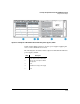
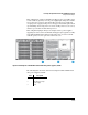
To achieve the 32 ports at 15.4 watts the PoE devices must be divided up and
connected to two different modules. Remember, as soon as a module is
installed into the switch, 22 watts is reserved for its use.
In order to use those watts, devices must be connected to that module or PoE
power must be disabled to all ports on that module.
If PoE power is disabled to all ports on a module the 22 watts that was reserved
for that module is returned to the pool of available watts and can be used by
another module’s ports.
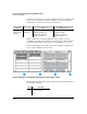
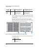
In this example the load must be balanced or split between two or three
modules in order to effectively use all 508 watts. The number of devices and
wattage must be split between the modules. This would also help limit the
effects of a single module failure. If one module fails, only the devices on that
module would lose power.
In this example, there are three modules in the chassis and therefore 22 watts
is reserved for each module. In order to use the 22 watts, PDs must be
connected to each module. Or all ports on one module could have the PoE
power disabled.
There is no redundant power with this configuration. If a power supply fails,
the remaining power supply can keep the switch running, but cannot supply
all the PoE power needed by the modules.
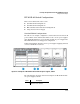
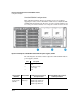
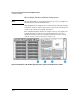
2 32 ports can receive up to 15.4 watts of
PoE power
3 Front
4 254 watts for PoE per power supply
5 Back
Label Description
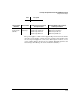
Source of Power
(PoE/PoE+)
Watts Available Number of Ports Powered and Average
watts/Port
Redundant Number of Ports Powered
and Average watts/Port
Two Internal
Power Supplies
(J9828A)
508 (without
redundancy)
16@ average 30 W each
32 @ average 15.4 W each
66 @ average 7.5 W each
123 @ average 4.0 W each
None