
HP Power over Ethernet (PoE/PoE+) Planning and Implementation Guide


7-4
Planning and Implementation for the HP 2620-PoE+ Switches
Planning the PoE Configuration
PoE/PoE+ Allocation Using LLDP Information
A PoE port can automatically configure certain PoE+ link partner devices if
the device supports advertising of its PoE needs.
By enabling PoE LLDP detection, available information about the power
requirements of the PD may be used by the switch to configure the power
allocation. The initial configuration for PoE ports may change if more accurate
configuration information is provided by way of LLDP.
For more configuration information, refer to the Management and
Configuration Guide for your switch at www.hp.com/networking/support. Auto
search on “2620”, select your switch model from the list, and click Display
selected. Then click on the links that have “Manuals” in them to get to the web
page that lists the available manuals.
Planning the PoE Configuration
This section assists you in building a PoE+ configuration. Using the following
examples you can plan, build, and connect PoE+ devices quickly and easily.
There are six configurations:
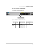
■ HP 2620-24-PPoE+ Switch
■ HP 2620-24-PoE+ Switch
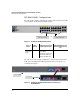
■ HP 2620-24-PoE+ Switch connecting an external power supply
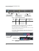
■ HP 2620-48-PoE+ Switch
■ HP 2620-48-PoE+ Switch connecting an external power supply
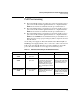
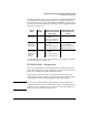
Each example shows a complete configuration. A table shows the PoE+ power
available to connected PoE+ devices when using just the switch and when
connecting an external power supply.
Once you have selected your specific configuration and the PoE+ power
provided, you then add up the maximum amount of power each device
requires (use maximum power in watts, usually found on a product’s data
sheet). Adjust this total maximum power figure by adding 16% to account for
possible line loss. This value must be less than the maximum power available
shown in the table for your configuration.