
HP Power over Ethernet (PoE/PoE+) Planning and Implementation Guide


8-4
Planning and Implementation for the HP 2910-PoE+ al Switches
Planning the PoE Configuration
Planning the PoE Configuration
This section assists you in building a PoE+ configuration. Using the following
examples you can plan, build, and connect PoE+ devices quickly and easily.
There are four configurations:
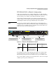
■ HP 2910-24G-PoE+ al Switch
■ HP 2910-24G-PoE+ al Switch connecting an external power supply
■ HP 2910-48G-PoE+ al Switch
■ HP 2910-48G-PoE+ al Switch connecting an external power supply
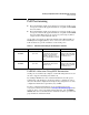
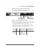
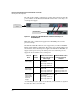
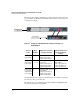
Each example shows a complete configuration. A table shows the PoE+ power
available to connected PoE+ devices when using just the switch and when
connecting an external power supply.
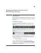
Once you have selected your specific configuration and the PoE+ power
provided, you then add up the maximum amount of power each device
requires (use maximum power in watts, usually found on a product’s data
sheet). Adjust this total maximum power figure by adding 16% to account for
possible line loss. This value must be less than the maximum power available
shown in the table for your configuration.