
HP Power over Ethernet (PoE/PoE+) Planning and Implementation Guide


10-4
Planning and Implementation for the HP 3500-PoE Switches
Planning the PoE Configuration
Planning the PoE Configuration
This section assists you in building a PoE configuration. Using the following
examples you can plan, build, and connect PoE devices quickly and easily.
There are four configurations for the HP 3500 Switches:
■ HP 3500-24-PoE Switch
■ HP 3500-24-PoE Switch connecting an external power supply
■ HP 3500-48-PoE Switch
■ HP 3500-48-PoE Switch connecting an external power supply
Each example shows a complete configuration. A table below the
configuration shows the PoE power available to connected PoE devices when
using just the switch.
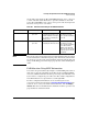
Once you have selected your specific configuration and the PoE power
provided, you then add up the maximum amount of power each device
requires (use maximum power in watts, usually found on a product’s data
sheet). Adjust this total maximum power figure by adding 16% to account for
possible line loss. This value must be less than the maximum power available
shown in the table for your configuration.
HP 3500-24-PoE Switch Configuration
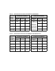
The table in this example configuration shows the PoE power available for
the HP 3500-24-PoE Switch using the internal power supply.
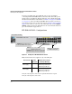
Figure 10-1. Example of an HP 3500-24-PoE Switch Using the Internal Power
Supply
All 24 ports can receive up to 15.4
watts of PoE power