HP Switch zl2 Modules Installation Guide Power over Ethernet
HP Switch zl2 Modules Installation Guide
© Copyright 2005 - 2014 Hewlett-Packard Development Company, L.P.
iii
iv
Contents HP Switch v2 zl Modules . . . . . . . . . . . . . . . . . . . . . . . . . . . . . . . . . . . . . . . . . . . 1 For the HP 5400R zl2 Switches . . . . . . . . . . . . . . . . . . . . . . . . . . . . . . . . . . 1 Network Interface Module LEDs . . . . . . . . . . . . . . . . . . . . . . . . . . . . . . . . . . . . . 5 Network Connectivity Modules Port LEDs . . . . . . . . . . . . . . . . . . . . . . . . . 5 Features . . . . . . . . . . . . . . . . . . . . . . . . . . . . . . . . . . . . . . . . . . .
Contents U.S.A. . . . . . . . . . . . . . . . . . . . . . . . . . . . . . . . . . . . . . . . . . . . . . . . . . . . . . 32 Canada . . . . . . . . . . . . . . . . . . . . . . . . . . . . . . . . . . . . . . . . . . . . . . . . . . . . . 32 Australia/New Zealand . . . . . . . . . . . . . . . . . . . . . . . . . . . . . . . . . . . . . . . . 32 Japan . . . . . . . . . . . . . . . . . . . . . . . . . . . . . . . . . . . . . . . . . . . . . . . . . . . . . . 32 Korea . . . . . . . . . . . . . . . . . . . . .
HP Switch v2 zl Modules HP Switch v2 zl Modules For the HP 5400R zl2 Switches Descriptions. The HP Switch v2 zl Modules are the second generation zl modules and provide a variety of improved network connectivity options for the HP 5400R zl2 switches. The following modules are currently available.
HP Switch v2 zl Modules Module Description HP 8-port 10-GbE SFP+ v2 zl Module (J9538A) 1 8 ports for installing any of the supported HP transceivers. The SFP+ ports do not support IEEE 802.3at PoE+. HP 8-port 10GBase-T v2 zl Module (J9546A) 2 8 twisted-pair ports with RJ-45 connectors for 10GBase-T operation over Category 6 or better 100-ohm UTP or STP cable. PoE is not supported on this module.
HP Switch v2 zl Modules Module Description HP 24-port Gig-T v2 zl Module (J9550A) 1 24 twisted-pair ports with RJ-45 connectors for 10/100/1000Base-T operation over Category 5 or better 100-ohm UTP or STP cable (category 5e recommended for Gigabit). All ports have the IEEE 802.3ab Auto MDI/MDI-X (HP Auto-MDIX) feature.This module does not support IEEE 802.3at PoE+.
HP Switch v2 zl Modules Module Description HP Advanced Services v2 zl Module with SSD (J9858A) The HP Advanced Services v2 zl module is a converged networking, computing, and virtualization solution inside the 5400 zl, 8200 zl, and 5400R zl2 switch families that hosts VMware vSphere(R) compatible virtual networking or business applications inside the switch. HP MSM775 zl Premium Controller Module (J9840A) The IEEE 802.
Network Interface Module LEDs Network Interface Module LEDs Network Connectivity Modules Port LEDs There are two LEDs for each port: ■ The Link LED lights green with a valid connection and orange if there is a fault or alert condition. ■ The Mode LED lights according to the LED mode selected on the chassis. The LED mode is selected on the Management Module for the 5400R zl2 switches,.
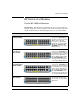
Features Features v2 zl Module Features Figure 1.
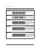
Features Figure 2.
Features The v2 zl Modules have the following features: ■ 8 All v2 zl modules share the following features: • auto-enabled ports—the ports are all configured to be ready for network operation as soon as a viable network cable is connected • auto-configuration—a default configuration is applied to the module when the switch is powered on and the module passes self test; this default configuration works well for most network installations • LEDs that provide information for each port on the link statu
Installing the Modules Installing the Modules Overview Before installing any module, ensure you have loaded the most current software for that module onto your switch, see page 1 for the V2 modules software version. You can install any of the modules into any of the HP networking chassis zl switches that have compatible module slots. HP 5400R zl2 Switches: ■ 5406R zl2 and all related bundles ■ 5412R zl2 and all related bundles “Hot Swap” Notes The SFPs can be “hot swapped”.
Installing the Modules Installing the Module in an Unused Slot Installation Precautions: ■ Static electricity can severely damage the electronic components on the modules. When handling and installing the modules in your switch, follow these procedures to avoid damage from static electricity: • Handle the module by its bulkhead or edges and avoid touching the components and the circuitry on the board.
Installing the Modules Figure 3. Example: Module being installed The following table shows label and description on how to install a module: Label Description 1, 3 Insert module into the guides and slide it in until it is fully inserted.
Installing the Modules Figure 4. Module fully installed Installing or Removing a SFP transceiver You can install or remove a SFP transceiver from the SFP v2 zl Module without having to power off the switch. Use only SFP transceivers. WARNING The HP SFPs are Class 1 laser devices. Avoid direct eye exposure to the beam coming from the transmit port. Caution Use only supported genuine HP SFP transceivers with your switch.
Installing the Modules Figure 5. Example: SFP transceiver being installed Removing the SFP transceivers: Disconnect the network cable from the transceiver before removing it from the module. Depending on when you purchased your transceiver, it may have either of three different release mechanisms: a plastic tab on the bottom, a wire bail, or a plastic collar.
Installing the Modules Verifying the Module is Installed Correctly Observe the Module Status LED for the slot in which the module is being installed, and the Test and Fault LEDs on the switch to verify the module is installed properly. Figure 6.
Installing the Modules Test ON briefly while the module is being tested, then OFF. Note: If the switch was powered off while the module was installed, when the switch is powered on, the Test LED will stay ON for the duration of the whole switch self test.
Installing the Modules Connecting the Network Cables Connect the appropriate network cables to the module's ports as shown in the table below. For more information on the cable specifications, see “Cabling and Technology Specifications” on page 27. Module 10/100/1000-T PoE zl Module Notes: • The RJ-45 ports on this module have the Auto-MDIX feature.
Installing the Modules Operation of these features depend on the port configurations being kept at Auto. If the configuration is changed to one of the available fixed options (for example, 100-Full Duplex), the port operates as an MDI-X port. In that case, to connect the module to another switch or hub, use a crossover cable; to connect to an end node, use a straight-through cable.
Installing the Modules Verifying the Network Connections Are Working Check the port LEDs for the newly-installed module to ensure the port(s) connected in the preceding step are operating correctly. Each port on the switch modules has Link and Mode LEDs near it as shown in the next illustration. Figure 7.
Installing the Modules • On = >1 Gbps • If the port is in AUTO, the spd mode LED will be off. Default Port Configuration If the slot in which you installed the module was empty the last time the switch was either rebooted or reset (or the power to the switch was cycled), then the module will use preconfigured default parameter values that will work for most networks.
Replacing or Removing a Module Replacing or Removing a Module Follow these procedures to replace one module with another, or to remove a module without replacing it: 1. Remove any network cables from the ports on the module. 2. If the module you want to remove has a shutdown button, make sure to shut down the module before removing it either by using the CLI shutdown command or by using the shutdown button. 3.
Troubleshooting Caution • If you will be installing another module in the slot, go to “Installing the Module in an Unused Slot” on page 10 and begin with step 2. • If you will not install another module in the slot (that is, leave it empty), then re-install a slot cover plate over the empty slot opening. For proper cooling and reduction of electromagnetic emissions, ensure a slot cover is installed on any unused slot. 6.
Customer Support Services Information Item 22 Information Location • details about the switch’s status including the OS (software) version, a copy of the switch configuration, a copy of the switch Event Log, and a copy of the switch status and counters information switch console: show tech command • copy of your network topology map, including network addresses assigned to the relevant devices your network records
Specifications Specifications Environmental Modules Temperature Module Operating J8726A 0° C to 55° C (32° F to 131° F) -40° C to 70° C (-40° F to 158° F) Non-Operating J9051A 0° C to 40° C (32° F to 104° F) -40° C to 70° C (-40° F to 158° F) J9052A 0° C to 40° C (32° F to 104° F) -40° C to 70° C (-40° F to 158° F) J9154A 0° C to 40° C (32° F to 104° F) -40° C to 70° C (-40° F to 158° F) J9534A 0° C to 55° C (32° F to 131° F) -40° C to 70° C (-40° F to 158° F) J9535A 0° C to 40° C (32° F
Specifications Modules Temperature Relative humidity: (non-condensing) J9154x only 15% to 95% at 40° C (104° F) 15% to 90% at 65° C (149° F) 15% to 90% at 40° C (104° F) 15% to 90% at 65° C (149° F) Maximum altitude: 3.0 km (10,000 ft) 4.6 km (15,000 ft) Network Connectivity Speeds and Technologies Table 1.
Specifications Technology Standards and Safety Compliance Table 2. Technology Standards and Safety Compliance Laser safety information Technology Compatible with these IEEE standards EN/IEC standard compliance SFP Lasers 10-T IEEE 802.3 10BASE-T 100-TX IEEE 802.3u 100BASE-TX 1000-T IEEE 802.3ab 1000BASE-T 10GBASE-T IEEE 802.3an 10GBASE-T 100-FX IEEE 802.3u 100BASE-FX EN/IEC 60825 Class 1 Laser Product Laser Klasse 1 100-BX IEEE 802.
Specifications Table 2. Technology Standards and Safety Compliance (Continued) Laser safety information Technology Compatible with these IEEE standards EN/IEC standard compliance 10-Gig SR IEEE 802.3ae 10GBASE-SR 10-Gig LRM X2 Lasers SFP+ Lasers EN/IEC 60825 Class 1M Laser Product Laser Klasse 1M Class 1 Laser Product Laser Klasse 1 IEEE 802.3aq 10GBASE-LRM EN/IEC 60825 Class 1 Laser Product Laser Klasse 1 Class 1 Laser Product Laser Klasse 1 10-Gig LR IEEE 802.
Specifications Cabling and Technology Specifications Table 3. Cabling Specifications 10 Mbps Operation Category 3, 4 or 5, 100-ohm unshielded twisted-pair (UTP) or shielded twisted-pair (STP) cable, complying with IEEE 802.3 10BASE-T specifications. 100 Mbps Operation Category 5, 100-ohm UTP or STP cable, complying with IEEE 802.3u 100BASE-TX specifications. 1000 Mbps Operation Category 5, 100-ohm 4-pair UTP or STP cable, complying with IEEE 802.
Specifications Attenuation, Near-End Crosstalk (NEXT), and Far-End Crosstalk (FEXT). Additionally, unlike the cables for 100BASE-TX, the 1000BASE-T cables must pass tests for Equal-Level Far-End Crosstalk (ELFEXT) and Return Loss. When testing your cabling, be sure to include the patch cables that connect the switch and other end devices to the patch panels on your site. The patch cables are frequently overlooked when testing cable and they must also comply with the cabling standards.
Specifications Table 4. Technology Distance Specifications(Continued) Technology Supported cable type Multimode fiber modal bandwidth Supported distances 100-BX single mode fiber N/A 0.
Specifications Mode Conditioning Patch Cord The following information applies to installations in which multimode fiberoptic cables are connected to a Gigabit-LX port or a 10-Gigabit LRM port. Multimode cable has a design characteristic called “Differential Mode Delay”, which requires the transmission signals be “conditioned” to compensate for the cable design and thus prevent resulting transmission errors.
Specifications Gigabit-LX port To network multimode cabling The multimode cable in the patch cord must match the characteristics of your network cable Mode Conditioning Patch Cord Single mode section plugs into Tx port on Gigabit-LX Transceiver or Gigabit-LX SFP Figure 9.
EMC Regulatory Statements EMC Regulatory Statements U.S.A. FCC Class A This equipment has been tested and found to comply with the limits for a Class A digital device, pursuant to Part 15 of the FCC Rules. These limits are designed to provide reasonable protection against interference when the equipment is operated in a commercial environment.
EMC Regulatory Statements Korea Taiwan European Community Declaration of Conformity These products are designed for operation with the HP switches that have zl module slots. Please see the Declarations of Conformity included in the Installation Guides for those products. Note For Conducted and Radiated Immunity in accordance with EN55024, the HP 8-port 10GBase-T v2 zl Module (J9546A) is limited to Performance Criteria A with shielded cable (Cat 6/6A).
Waste Electrical and Electronic Equipment (WEEE) Statements Waste Electrical and Electronic Equipment (WEEE) Statements Disposal of Waste Equipment by Users in Private Household in the European Union This symbol on the product or on its packaging indicates that this product must not be disposed of with your other household waste.
Waste Electrical and Electronic Equipment (WEEE) Statements Élimination des appareils mis au rebut par les ménages dans l'Union européenne Le symbole apposé sur ce produit ou sur son emballage indique que ce produit ne doit pas être jeté avec les déchets ménagers ordinaires. Il est de votre responsabilité de mettre au rebut vos appareils en les déposant dans les centres de collecte publique désignés pour le recyclage des équipements électriques et électroniques.
Waste Electrical and Electronic Equipment (WEEE) Statements Nolietotu iekārtu iznīcināšanas noteikumi lietotājiem Eiropas Savienības privātajās mājsaimniecībās Šāds simbols uz izstrādājuma vai uz tā iesaiņojuma norāda, ka šo izstrādājumu nedrīkst izmest kopā ar citiem sadzīves atkritumiem. Jūs atbildat par to, lai nolietotās iekārtas tiktu nodotas speciāli iekārtotos punktos, kas paredzēti izmantoto elektrisko un elektronisko iekārtu savākšanai otrreizējai pārstrādei.
Waste Electrical and Electronic Equipment (WEEE) Statements Likvidácia vyradených zariadení v domácnostiach v Európskej únii Symbol na výrobku alebo jeho balení označuje, že daný výrobok sa nesmie likvidovať s domovým odpadom. Povinnosťou spotrebiteľa je odovzdať vyradené zariadenie v zbernom mieste, ktoré je určené na recykláciu vyradených elektrických a elektronických zariadení.
Waste Electrical and Electronic Equipment (WEEE) Statements 38
5400zl Switches Installation and Getting Startd Guide Technology for better business outcomes To learn more, visit www.hp.com/networking © Copyright 2005-2014 Hewlett-Packard Development Company, L.P. The information contained herein is subject to change without notice. The only warranties for HP products and services are set forth in the express warranty statements accompanying such products and services. Nothing herein should be construed as constituting an additional warranty.