
IPv6 Configuration Guide K/KA/KB.15.15

copy
When specified, the value of the TTL field from the IPv6 header is used in the
IPv4 header.
Default : 64 seconds
Example 183 Configuring a TTL for the Packet
HP Switch(tunnel-3)# tunnel ttl 100
Example: Manual 6in4 Tunneling
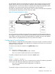
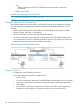
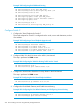
This example creates an IPv6 6in4 tunnel, which allows IPv6 hosts in one network to exchange
IPv6 data with hosts in another IPv6 network by using the IPv4 tunneling infrastructure. In this
example:
• All IPv6 traffic between hosts in the 3000::/64 and the 4000::/64 networks is tunneled
through Switch B and Switch C, respectively.
• Switch B and Switch C are the manually configured endpoints.
• IPv6 traffic entering the tunnel endpoints is encapsulated with an IPv4 header based on the
6in4 configuration, and then routed through the IPv4 network using Switch A as the first hop.
• Static IPv6 routes are used to route into the tunnel interfaces.
Figure 28 Example of Manual 6in4 Tunneling
Configure Switch B
1. Configure the Tunnel Endpoint for Switch B
The tunnel endpoint for Switch B is configured with:
• Mode—6in4
• Source—encapsulation information for the IPv4 header indicating the source IPv4 address
• Destination—encapsulation information for the IPv4 header indicating the destination
IPv4 address
• IPv6 Address—IPv6 network assigned to the interface (much like VLAN assignments).
Enables IPv6 on the interface. It is required in order to route over the interface.
266 IPv6 Tunneling Over IPv4 Using Manually Configured Tunnels