
Multicast and Routing Guide K/KA/KB.15.15


Used on a pair of ABRs at opposite ends of a virtual link in the same area to
configure the virtual link connection.
area-id This must be the same for both ABRs in the link and is the area
number of the virtual link transit area in either decimal or dotted
decimal format.
ip-address On an ABR directly connected to the backbone area, this value
must be the IP address of an ABR (in the same area) needing a
virtual link to the backbone area as a substitute for a direct
physical connection.
On the ABR that needs the virtual link to the backbone area, this
value must be the IP address of the ABR (in the same area) having
a direct physical connection to the backbone area.
Example
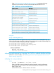
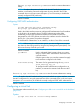
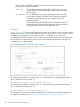
Figure 35 (page 160) shows an OSPF ABR, routing switch "A" that lacks a direct connection to the
backbone area (area 0.) To provide backbone access to routing switch "A," you can add a virtual
link between routing switch "A" and routing switch "C," using area 1 as a transit area.
To configure the virtual link, define it on the routers that are at each end of the link. No configuration
for the virtual link is required on the other routers on the path through the transit area (such as
routing switch "B" in this example.)
Figure 35 Defining OSPF virtual links within a network
To configure the virtual link on routing switch "A," enter the following command specifying the
area 1 interface on routing switch "C":
HP Switch(ospf)# area 1 virtual-link 209.157.22.1
To configure the virtual link on routing switch "C," enter the following command specifying the
area 1 interface on routing switch "A":
HP Switch(ospf)# area 1 virtual-link 10.0.0.1
For descriptions of virtual link interface parameters you can either use in their default settings or
reconfigure as needed, see “Changing the dead interval on a virtual link” (page 161).
160 Open Shortest Path First Protocol (OSPF)