
Multicast and Routing Guide K/KA/KB.15.15
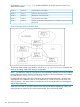
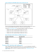
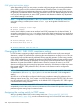

For example, in Figure 39 (page 192), the DR and BDR for 10.10.10.0 network in area 5 are
determined as follows:
Cannot become a DR or BDRPriority: 0Router A
DR for the 10.10.10.0 networkPriority: 1Router B
BDR for the 10.10.10.0 networkPriority: 2Router C
Cannot become a DR or BDRPriority: 3Router D
Becomes the new BDR if router B becomes unavailable and router C becomes
the new DR
Priority: 4Router E
Figure 39 Example of DRs in an OSPF area
To learn the router priority on an interface, use the show ip ospf interface command and
check the Pri setting under OSPF interface configuration.
NOTE: By default, the router ID is typically the lowest-numbered IP address or the lowest-numbered
(user-configured) loopback interface configured on the device. For more information or to change
the router ID, see “Changing the router ID” (page 117).
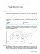
If multiple networks exist in the same OSPF area, the recommended approach is to ensure that
each network uses a different router as its DR. Otherwise, if a router is a DR for more than one
network, latency in the router could increase because of the increased traffic load resulting from
multiple DR assignments.
When only one router on an OSPF network claims the DR role despite neighboring routers with
higher priorities or router IDs, this router remains the DR. This is also true for BDRs.
192 Open Shortest Path First Protocol (OSPF)