
Multicast and Routing Guide K/KA/KB.15.15

How IGMP proxy forwarding works
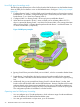
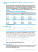
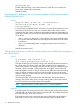
The following steps illustrate how to flood a flow from the PIM-SM domain into the PIM-DM domain
when an IGMP join for that flow occurs in the PIM-DM domain. See figure “IGMP proxy example”
(page 32).
1. Configure Routing Switch 1 with the IGMP proxy forwarding function to forward joins toward
Border Router 1; in addition, configure Routing Switch 1 to forward joins from VLAN 1 toward
Border Router 2, as is VLAN 4 on Routing Switch 3.
2. Configure VLAN 2 on Routing Switch 2 to forward joins toward Border Router 1.
3. When the host connected in VLAN 1 issues an IGMP join for multicast address 235.1.1.1,
the join is proxied by Routing Switch 1 onto VLAN 2 and onto VLAN 4. The routing information
table in Routing Switch 1 indicates that the packet to Border Router 1 and Border Router 2 is
on VLAN 2 and VLAN 4, respectively.
Figure 5 IGMP proxy example
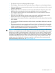
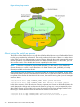
4. Routing Switch 2 then proxies the IGMP join into VLAN 3, which is connected to Border Router
1.
5. Border Router 1 uses PIM-SM to find and connect to the multicast traffic for the requested
traffic. The traffic is flooded into the PIM-DM network where it is routed to the original joining
host.
6. Additionally, the join was proxied from Routing Switch 3 to Border Router 2. At first, both
border routers will flood the traffic into the PIM-DM domain. However, PIM-DM only forwards
multicasts based on the shortest reverse path back to the source of the traffic as determined
by the unicast routing tables (routing FIB.) Only one multicast stream is sent to the joining host.
This configuration provides a redundant in case the first fails.
Operating notes for IGMP proxy forwarding
• You can configure up to 12 multicast domains, which indicate a range of multicast addresses
and the IP address of the PIM-SM/PIM-DM border router.
• You must give each domain a unique name, up to 20 characters.
32 Multimedia Traffic Control with IP Multicast (IGMP)