
Multicast and Routing Guide K/KA/KB.15.15
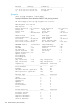
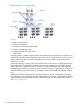
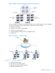

Figure 66 Solution 1 — Campus iBGP
Devices
A WAN Gateway Router
B Enterprise Core Router
C Enterprise Core Router (Campus Edge)
D Campus Core Routing Switch
E Campus Distribution Routing Switch
F Edge Switch
In the figure above, multiple campus domains are segmented by using BGP in the enterprise core.
Traditionally, HP solutions have been used with devices E and F, facing the client or server network
edges. With the introduction of BGP functionality, it becomes possible to position solutions at
locations B, C, and D.
With proper filtering, a routing switch with 20,000 routes can be used in an iBGP deployment. A
device at location C represents the boundary between interior gateway protocol (IGP) domains,
and the BGP core. Functionality used on this device includes redistribution with route maps and
the establishment of BGP communities. Devices at location B require AS path filtering. All locations
within the BGP AS require the remaining “Foundation” features (Route Reflection, Refresh, Multihop,
etc..)
Additional Autonomous Systems may be configured within a network, resembling the enterprise
core module as shown in the diagram. With larger enterprise customers, it is likely that an AS that
is directly adjacent to IGP campus modules will be the location for HP foundation BGP solutions.
See Figure 67 (page 337).
336 Border Gateway Protocol (BGP)