HP Switch Software Basic Operation Guide Abstract This switch software guide is intended for network administrators and support personnel, and applies to the switch models listed on this page unless otherwise noted. This guide does not provide information about upgrading or replacing switch hardware. The information in this guide is subject to change without notice. Applicable Products Applies to all switch series.
© Copyright 2013 Hewlett-Packard Development Company, L.P. Confidential computer software. Valid license from HP required for possession, use or copying. Consistent with FAR 12.211 and 12.212, Commercial Computer Software, Computer Software Documentation, and Technical Data for Commercial Items are licensed to the U.S. Government under vendor's standard commercial license. The information contained herein is subject to change without notice.
Contents 1 Commands found in the Basic Operation Guide.............................................7 2 Getting started...........................................................................................9 Initial switch set-up....................................................................................................................9 Recommended minimal configuration.....................................................................................9 Using the switch setup screen.............
5 Using the HP WebAgent...........................................................................44 Overview..............................................................................................................................44 General features.....................................................................................................................45 Starting the WebAgent............................................................................................................
Viewing the startup-config file status with multiple configuration enabled...............................77 Displaying the content of a specific startup-config file.........................................................77 Changing or overriding the reboot configuration policy...........................................................78 Managing startup-config files in the switch............................................................................79 Renaming an existing startup-config file..........
Specifying the source IP address........................................................................................121 The source IP selection policy........................................................................................122 Displaying the source IP interface information......................................................................123 Error messages................................................................................................................
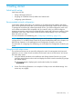
1 Commands found in the Basic Operation Guide NOTE: Certain commands are not supported on all switch models.
Table 1 List of commands (continued) 8 Command Page menu 18 redo 40 reload after 71 reload at 71 rename config 79 repeat 41 session interactive-mode 37 session show-message-type 36 show 107 show banner 15 show config 90 show config files 77 show config interface 90 show config status 51 show console 96 show flash 136 show ip route 116 show ip source-interface 124 show reload 73 show running-config 84 show running-config interface 84 show session 38
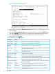
2 Getting started Initial switch set-up Initial setup includes: • setting a Manager password • assigning an IP (Internet Protocol) address and subnet mask • configuring optional banners Recommended minimal configuration In the factory default configuration, the switch has no IP (Internet Protocol) address and subnet mask, and no passwords. In this state, it can be managed only through a direct console connection.
Figure 1 Example Switch Setup screen 3. 4. 5. 6. 7. Use the Tab key to select the Manager Password field and enter a manager password of up to 16 characters. Tab to the IP Config (DHCP/Bootp) field and use the Space bar to select the Manual option. Tab to the IP Address field and enter the IP address that is compatible with your network. Tab to the Subnet Mask field and enter the subnet mask used for your network. Press Enter, then S (for Save).
Table 2 Setup screen field descriptions (continued) Parameter Default Subnet Mask xxx.xxx.xxx.xxx Recommended; If you entered an IP address, then enter a subnet mask compatible with your network.* * The IP address and subnet mask assigned for the switch must be compatible with the IP addressing used in your network. For more on IPv4 addressing, see “Configuring IP addressing” (page 105). For IPv6 addressing topics, refer to the latest IPv6 Configuration Guide for your switch.
This command defines the single character used to terminate the banner text and enables banner text input. You can use any character except a blank space as a delimiter. The no form of the command disables the login banner feature. The switch allows up to 3070 banner characters, including blank spaces and CR-LF ([Enter]). (The tilde “~“ and the delimiter defined by banner motd are not allowed as part of the banner text.
Example 2 Show banner motd output HP Switch(config)# show banner motd Banner Information Configured Banner: This is a private system maintained by the Allied Widget Corporation. Unauthorized use of this system can result in civil and criminal penalties! Example 3 Banner in the switch’s running-config file HP Switch (config)# show running Running configuration: ; J8697A Configuration Editor; Created on release #K.15.12.
• If a banner is configured, the switch does not allow configuration with ssh version 1 or ssh version 1-or-2. Attempting to do so produces the following error message in the CLI: Banner has to be disabled first.
The following escape characters are supported: \" double q \’ single quote \` forward quote \\ backslash \f form feed \n newline \r carriage return \t horizontal tab \v vertical tab Example 7 Configuring the banner message using escape characters within double quote delimiters HP Switch(config)# banner motd "You can use the \’banner motd\’ CLI command in non-interactive mode.\n\n\tThe banner motd command will support escape characters.
Example 9 Configuring the banner message using an alternate delimiter of ‘#’ HP Switch(config)# banner motd # Enter TEXT message. End with the character ‘#’ You can use the \’banner motd\’ CLI command in non-interactive mode.\n\n\t The banner motd command will support escape characters.
3 Using the Menu Interface Overview This chapter describes the following features: • Overview of the Menu Interface, 17 • Starting and ending a Menu session, 18 • The Main Menu, 20 • Screen structure and navigation, 20 • Rebooting the switch, 22 The menu interface operates through the switch console to provide you with a subset of switch commands in an easy-to-use menu format enabling you to: • Perform a "quick configuration" of basic parameters, such as the IP addressing needed to provide manage
Menu interaction with other interfaces. • The menu interface displays the current running-config parameter settings. You can use the menu interface to save configuration changes made in the CLI only if the CLI changes are in the running config when you save changes made in the menu interface. (For more on how switch memory manages configuration changes, see Chapter 6, “Switch Memory and Configuration”.
Figure 2 Example of the Main Menu with Manager Privileges For a description of Main Menu features, see “Main Menu features” (page 20). NOTE: To configure the switch to start with the menu interface instead of the CLI, go to the Manager level prompt in the CLI, enter the setup command, and in the resulting display, change the Logon Default parameter to Menu. For more information, see the Installation and Getting Started Guide you received with the switch.
Rebooting the switch terminates the menu session, and, if you are using Telnet, disconnects the Telnet session. (See “Rebooting the switch” (page 22).) 3. Exit from the terminal program, turn off the terminal, or close the Telnet application program. Main Menu features The Main Menu gives you access to these Menu interface features: • Status and Counters: Provides access to display screens showing switch information, port status and counters, and port and VLAN address tables.
Figure 4 Elements of the screen structure "Forms" design. The configuration screens, in particular, operate similarly to a number of PC applications that use forms for data entry. When you first enter these screens, you see the current configuration for the item you have selected. To change the configuration, the basic operation is to: 1. Press [E] to select the Edit action. 2. Navigate through the screen making all the necessary configuration changes. (See Table 3 on page 21.) 3.
Table 3 How to navigate the Menu interface (continued) Task: Actions: 6. If you are finished editing parameters in the displayed screen, press [Enter] to return to the Actions line and do one of the following: • To save and activate configuration changes, press [S] (for the Save action). This saves the changes in the startup configuration and also implements the change in the currently running configuration. (See Chapter 6, "Switch Memory and Configuration".
Figure 5 The Reboot Switch option in the Main Menu Rebooting to activate configuration changes. Configuration changes for most parameters in the menu interface become effective as soon as you save them. However, you must reboot the switch in order to implement a change in the Maximum VLANs to support parameter. To access this parameter, go to the Main Menu and select: 2. Switch Configuration 8. VLAN Menu 1. VLAN Support.
NOTE: Executing the write memory command in the CLI does not affect pending configuration changes indicated by an asterisk in the menu interface. That is, only a reboot from the menu interface or a boot or reload command from the CLI will activate a pending configuration change indicated by an asterisk.
Where to go from here This chapter provides an overview of the menu interface and how to use it. The following table indicates where to turn for detailed information on how to use the individual features available through the menu interface. Option: Turn to: To use the Run Setup option Refer to the Installation and Getting Started Guide shipped with the switch.
4 Using the Command Line Interface (CLI) Overview The CLI is a text-based command interface for configuring and monitoring the switch. The CLI gives you access to the switch’s full set of commands while providing the same password protection that is used in the web browser interface (WebAgent) and the menu interface. Accessing the CLI Like the menu interface, the CLI is accessed through the switch console, and in the switch’s factory default state, is the default interface when you start a console session.
Example 10 CLI log-on screen with password(s) set HP J8697A Switch 5406zl Software revision K.15.12.0001 Copyright (C) 1991-2013 Hewlett-Packard Development Company, L.P. RESTRICTED RIGHTS LEGEND Confidential computer software. Valid license from HP required for possession, use or copying. Consistent with FAR 12.211 and 12.212, Commercial Computer Software, Computer Software Documentation, and Technical Data for Commercial Items are licensed to the U.S. Government under vendor's standard commercial license.
Operator privileges At the Operator level you can examine the current configuration and move between interfaces without being able to change the configuration. A ">" character delimits the Operator-level prompt. For example: HP Switch>_ (Example of the Operator prompt.) When using enable to move to the Manager level, the switch prompts you for the Manager password if one has already been configured.
Manager privileges Manager privileges give you three additional levels of access: Manager, Global Configuration, and Context Configuration. A "#" character delimits any Manager prompt. For example: (Example of the Manager prompt.) HP Switch#_ • Manager level: Provides all Operator level privileges plus the ability to perform system-level actions that do not require saving changes to the system configuration file.
Table 4 Privilege level hierarchy (continued) Privilege Level Example of Prompt and Permitted Operations exit Terminate the current session (same as logout). Manager Privilege Manager Level HP Switch# Perform system-level actions such as system control, monitoring, and diagnostic commands, plus any of the Operator-level commands. For a list of available commands, enter ? at the prompt.
settings for that parameter. For example if you use the menu interface to configure an IP address of "X" for VLAN 1 and later use the CLI to configure a different IP address of "Y" for VLAN 1, then "Y" replaces "X" as the IP address for VLAN 1 in the running-config file. If you subsequently execute write memory in the CLI, then the switch also stores "Y" as the IP address for VLAN 1 in the startup-config file.
Example 12 The Manager-level command listing HP Switch# ? boot clear Reboot the device. Clear table/statistics or authorized client public keys. configure Enter the Configuration context. copy Copy datafiles to/from the switch. debug Enable/disable debug logging. end Return to the Manager Exec context. erase Erase stored data files. getMIB Retrieve and display the value of the MIB objects specified kill Kill other active console, telnet, or ssh sessions. licenses Manage premium features.
(Differentiated-Services Codepoint) value and 802.1p priority. type-of-serviceConfigure the Type-of-Service method the device uses to prioritize IP traffic. Listing commands options You can use the CLI to remind you of the options available for a command by entering command keywords followed by ?.
Example 14 Context-sensitive command-list help HP Switch> help enable exit link-test logout . . . Enter the Manager Exec context. Return to the previous context or terminate current console/telnet session if you are in the Operator context level. Test the connection to a MAC address on the LAN Terminate this console/telnet session. Displaying Help for an individual command. Syntax: help This option displays Help for any command available at the current context level.
HP Switch(eth-Trk1)# HP Switch(eth-C5-C8)# ? HP Switch(eth-C5-C8)# ? Lists the commands you can use in the port or static trunk context, plus the Manager, Operator, and context commands you can execute at this level. Figure 8 Context-specific commands affecting port context VLAN context. Includes VLAN-specific commands that apply only to the selected VLAN, plus Manager and Operator commands. The prompt for this mode includes the VLAN ID of the selected VLAN.
Figure 9 Context-specific commands affecting VLAN context Return message types with CLI commands When a CLI command returns a message, that message is now prefixed with a category describing the type, as follows: • Error • Warning • Information Syntax: session show-message-type [ enable | [disable]] When enabled, the CLI return messages are prefixed with string that indicates the type of message. Entered at the manager level.
Example 16 Message prefixes HP Switch(config)# router rip Error: IP Routing support must be enabled first. HP Switch(config)# qinq mixed vlan Warning: This command will reboot the device. Any prior configuration on this config file will be erased and the device will boot up with a default configuration for the new qinq mode.
Example 19 CLI interactive mode enabled HP Switch(config)# show session Show Message Type: Enabled CLI Interactive Mode: Enabled Interactive commands requiring additional options Interactive commands that require input other than yes or no are not affected when CLI interactive mode is disabled. A warning message is displayed when these commands are executed, for example: Interactive mode is disabled; This command will be ignored. Enable cli-interactive-mode to use this command.
Banner motd command with non-interactive mode The use of escape characters allows the banner motd command to be used in non-interactive mode for multiple message lines. In non-interactive mode, you can create a banner message enclosed in double quotes or other delimiter that uses escape characters within the delimiters. Other existing CLI commands do not support the escape characters.
Example 21 The running config file with banner motd configured in non-interactive mode HP Switch(config)# show running-config Running configuration: ;J8693A Configuration Editor; Created on release #K.15.10.0001 hostname "HP Switch" vlan 1 name "DEFAULT_VLAN" untagged 1-48, a1-a4 ip address dhcp-bootp exit banner motd "You can use the \’banner motd\’ CLI command in non-interactive mode.\n\n\tThe banner motd command will support escape characters.
Syntax: repeat [cmdlist] [count] [delay] Repeats execution of a previous command. Repeats the last command by default until a key is pressed. cmdlist: If a number or range of numbers is specified, the command repeats the nth most recent commands (where "n" is the position in the history list). count: Repeats the command for the number of times specified. delay: The command repeats execution after a delay for the number of seconds specified.
Creates a shortcut alias name to use in place of a commonly used command. The alias command is executed from the current config context. name: Specifies the new command name to use to simplify keystrokes and aid memory. command: Specifies an existing command to be aliased. The command must be enclosed in quotes. Use the no form of the command to remove the alias. For example, if you use the show interface custom command to specify the output, you can configure an alias for the command to simplify execution.
Example 26 Alias commands and their configurations HP Switch(config)# show alias Name ---------------sc sic Command -----------------------------show config show int custom 1-4 port name: 4 type vlan intrusion speed enabled mdi CLI shortcut keystrokes Keystrokes Functions [Ctrl] [A] Jumps to the first character of the command line. [Ctrl] [B] or ‘←’ Moves the cursor back one character. [Ctrl] [C] Terminates a task and displays the command prompt. [Ctrl] [D] Deletes the character at the cursor.
5 Using the HP WebAgent Overview The HP web browser interface (WebAgent) built into the switch lets you easily access the switch from a web browser.
General features The WebAgent includes this information: • • • • Home ◦ Quick Setup—Name, contact, IP, and VLAN information ◦ Status—Information about system uptime, switch addresses and serial number, VLANs, power, redundancy status, alert log, and utilization statistics System ◦ Logging—Fault detection, alert log ◦ SNMP—Community name and access, trap receivers, link status change ◦ Updates/Downloads—Configuration files, software images ◦ Redundancy—Management module status, fabric module
• Troubleshooting ◦ Ping/Link Test—Ping test details, link test details ◦ Configuration Report—Running config file information ◦ Core dump—Management/Interface modules enabled/disabled, list of core dump files for downloading ◦ Port Mirroring—Enabled/disabled Figure 10 Example of Status Screen for the WebAgent Starting the WebAgent Port Mirroring—Enabled/disabled • Using a standalone web browser on a network connection from a PC or UNIX workstation that is directly connected to your network or c
10.11.12.195 [Enter] (example of an IP address) The Home page of the WebAgent displays in the right pane and a navigation tree displays in the left pane. You can access all the WebAgent features from the navigation tree. Tasks for your first WebAgent session Viewing the “First Time Install” window When you access the WebAgent for the first time, the Alert log contains a “First Time Install” alert.
1. 2. 3. 4. In the navigation tree, select Security > Device Passwords. The Device Passwords screen displays. Click on Change on the right side of the screen. The pane expands to allow you to enter information. Enter a username, password, and access level. Click on Save to save your entries. NOTE: Passwords assigned in the WebAgent will overwrite previous passwords assigned in either the WebAgent, the CLI, or the menu interface.
Figure 12 Example of WebAgent access from PCM+ Connecting to the WebAgent from HP PCM+ 49
6 Switch memory and configuration Overview This chapter describes: • How switch memory manages configuration changes • How the CLI implements configuration changes • How the menu interface and WebAgent implement configuration changes • How the switch provides software options through primary/secondary flash images • How to use the switch’s primary and secondary flash options, including displaying flash information, booting or restarting the switch, and other topics Configuration file management Th
subsequently reboots for any reason, it will resume operation using the new configuration instead of the configuration previously defined in the startup-config file. There are three ways to save a new configuration: • In the CLI: Use the write memory command. This overwrites the current startup-config file with the contents of the current running-config file. • In the menu interface: Use the Save command.
How to use the CLI to view the current configuration files. Use show commands to view the configuration for individual features, such as port status or Spanning Tree Protocol. However, to view either the entire startupconfig file or the entire running-config file, use the following commands: • show config— Displays a listing of the current startup-config file. • show running–config— Displays a listing of the current running-config file.
HP Switch(config)# interface e a5 speed-duplex auto-10 After you are satisfied that the link is operating properly, you can save the change to the switch’s permanent configuration (the startup-config file) by executing the following command: HP Switch(config)# write memory The new mode (auto-10) on port A5 is now saved in the startup-config file, and the startup-config and running-config files are identical.
NOTE: If you use the CLI to make a change to the running-config file, you should either use the write memory command or select the save option allowed during a reboot (Figure 17, above) to save the change to the startup-config file.
NOTE: This feature does not change the system defaults. The custom default configuration file is automatically used when the startup configuration file is erased. It has no effect on what is loaded onto the switch when a remotely stored configuration file is restored. The default configuration file can be customized using commands at the CLI prompt or by copying a configuration file with the desired configuration using TFTP, USB, or XMODEM copy commands.
Syntax: copy tftp default-config Copies the stored configuration file on the TFTP server specified by to the custom default configuration file. Example 31 Copying a stored config file to the default config file using TFTP HP Switch(config)# copy tftp default-config 10.10.10.1 stored_config.cfg Using XMODEM To copy a configuration file to the custom default configuration file using XMODEM, use the copy xmodem default-config command.
Using USB To transfer a custom default configuration file off the switch using USB, enter the following command. Syntax: copy default-config usb stored_config.cfg Copies the custom default configuration file to the stored_config.cfg file on the USB device. Using SFTP and SCP to transfer the custom configuration While the switch supports an SSH server with SCP and/or SFTP running on it, the switch is not an SCP or SFTP client.
Example 35 Erasing the startup config file when a default custom config file exists HP Switch(config)# erase startup-config Configuration will be deleted, and existing login passwords removed, and device rebooted (using the custom default configuration), continue [y/n]? If a custom default configuration file does not exist and the erase startup-config command is executed, the current active configuration is erased and the switch is booted with the system default configuration.
Example 39 Output for custom default configuration file HP Switch(config)# show default-config Custom default configuration: ; J8693A Configuration Editor; Created on release #K.15.12.
Using the menu and WebAgent to implement configuration changes configuration file The menu and WebAgent offer these advantages: • Quick, easy menu or window access to a subset of switch configuration features • Viewing several related configuration parameters in the same screen, with their default and current settings • Immediately changing both the running-config file and the startup-config file with a single command Menu: implementing configuration changes You can use the menu interface to simultane
Rebooting from the menu interface • Terminates the current session and performs a reset of the operating system • Activates any configuration changes that require a reboot • Resets statistical counters to zero To Reboot the switch, use the Reboot Switch option in the Main Menu. (Note that the Reboot Switch option is not available if you log on in Operator mode; that is, if you enter an Operator password instead of a manager password at the password prompt.
Figure 17 Indication of a configuration change requiring a reboot WebAgent: implementing configuration changes You can use the WebAgent to simultaneously save and implement a subset of switch configuration changes without having to reboot the switch. That is, when you save a configuration change, you simultaneously change both the running-config file and the startup-config file. For online help with configuring changes in the WebAgent, click on the "?" in the WebAgent screen.
Syntax: erase all [zeroize] Erases all management module files, including configuration files, core dumps, password files, crypto-key files, etc. Software images are not erased. When executed without the zeroize option, files are removed, but the flash storage is not zeroized. The data is still physically present in the flash. The flash can be removed from the switch and the data recovered with file recovery tools. [zeroize]: Zeroizes the file storage of the management modules.
Using Primary and Secondary flash image options The switches covered in this guide feature two flash memory locations for storing switch software image files: • Primary Flash: The default storage for a switch software image. • Secondary Flash: The additional storage for either a redundant or an alternate switch software image. With the Primary/Secondary flash option you can test a new image in your system without having to replace a previously existing image.
Example 44 Different flash image versions HP Switch(config)# show flash Image Size(Bytes) Date -------------- -------Primary Image : 7493854 03/21/10 Secondary Image : 7463821 03/23/10 Version ------------K.15.01.0001 K.15.01.0001 Boot Rom Version: K.15.08 Default Boot : Primary Determining which flash image versions are installed. The show version command displays which software version the switch is currently running and whether that version booted from primary or secondary flash.
event that the primary image is corrupted, as a result of an interruption, the switch will reboot from secondary flash and you can either copy the secondary image into primary or download another image to primary from an external source. Local switch software replacement and removal This section describes commands for erasing a software version and copying an existing software version between primary and secondary flash.
For example, to copy the image in secondary flash to primary flash: 1. Verify that there is a valid flash image in the secondary flash location. The following figure indicates that a software image is present in secondary flash. (If you are unsure whether the image is secondary flash is valid, try booting from it before you proceed, by using boot system flash secondary.
Example 48 Show flash listing after erasing Primary flash HP Switch# show flash Compressed Primary Code size = 0 Compressed Secondary code size = 2555802 Boot ROM Version : K.15.19 Default Boot : Secondary In redundant management systems, this command will erase the selected flash in both the active and the standby management modules. If redundancy has been disabled or the standby module has failed selftest, this command only affects the active management module.
Table 6 Comparing the boot and reload commands Actions Included in Boot? Included in Reload Note Save all configuration changes since the last boot or reload Optional, with prompt Optional with reload , when prompt displays. Not saved with reload at/after commands; No prompt is displayed. Config changes saved to the startup-config file if "y" is selected (reload command). Perform all system self-tests Yes No The reload command provides a faster system reboot.
Note: This is changed from always booting from primary flash. You are prompted with a message which will indicate the flash being booted from. system: Boots the switch. You can specify the flash image to boot from. When using redundant management, boots both the active and standby management modules. config: You can optionally select a configuration file from which to boot.
Example 52 Boot command with secondary flash option HP Switch(config)# boot system flash secondary System will be rebooted from secondary image. Do you want to continue [y/n]? In the above example, typing either a ‘y’ or ‘n’ at the second prompt initiates the reboot operation. Using the fastboot feature. The fastback command allows a boot sequence that skips the internal power-on self-tests, resulting in a faster boot time.
Enables a scheduled warm reboot of the switch. The switch boots up with the same startup config file and using the same flash image as before the reload. CAUTION: When using redundant management, the reload at/after command causes a switchover at the scheduled time to the other management module, which may not be running the same software image or have the same configurations. Parameters include: • after: Schedules a warm reboot of the switch after a given amount of time has passed.
Syntax: [no] reload [[after <[[DD:]HH:]MM>] | [[at HH:MM[:SS] [MM/DD[/[YY]YY]]]] | [[module ]]] When specified with the module parameter, initiates a reload of the module in the specified slot or slots by turning the slot power off, then on again. A valid slot or range of slots must be specified. The at and after parameters are not allowed with the module option. The no version of the command is not valid with the module option.
Example 56 The scheduled reload at information HP Switch(config)# reload at 23:45 Reload scheduled at 23:45:47 6/16/2012 (in 0 days, 1 hours, 41 minutes HP Switch(config)# show reload at Reload scheduled for 23:45:47 06/16/2012 (in 0 days, 1 hours, 40 minutes) HP Switch(config)# show reload after Reload scheduled for 23:45:47 6/16/2012 (in 0 days, 1 hours, 40 minutes) Example 57 The scheduled reload after information HP Switch(config)# reload after 35 Reload scheduled in 0 days, 0 hours, 35 minutes HP Swit
Figure 18 Optional reboot process While you can still use remote storage for startup-config files, you can now maintain multiple startup-config files on the switch and choose which version to use for a reboot policy or an individual reboot.
1. 2. Reboot the switch through the Primary boot path using the startup-config file named backupconfig. Use the CLI to make configuration changes in the running-config file, and then execute write-mem. The result is that the startup-config file used to reboot the switch is modified by the actions in step 2. Figure 19 Example of reboot process and making changes to the startup-config file Creating an alternate startup-config file.
Example 60 Switch memory assignments after the first reboot from software supporting multiple configuration HP Switch(config)# show config files Configuration files: id | act pri sec | name ---+-------------+----------------------------------------------1 | | oldConfig 2 | * * * | workingConfig 3 | | In the above state, the switch always: • Uses the workingConfig file to reboot The commands described later in this section enable you to view the current multiple configuration status, manage multiple start
Syntax: show config This command displays the content of the specified startupconfig file in the same way that the show config command displays the content of the default (currently active) startupconfig file. Changing or overriding the reboot configuration policy Command Page startup-default [ primary | secondary ] config Below boot system flash config 79 You can boot the switch using any available startup-config file.
For example, suppose: • Software release “A” is stored in primary flash and a later software release is stored in secondary flash. • The system operator is using memory slot 1 for a reliable, minimal configuration (named minconfig) for the software version in the primary flash, and slot 2 for a modified startup-config file (named newconfig) that includes untested changes for improved network operation with the software version in secondary flash.
This command changes the name of an existing startupconfig file. A file name can include up to 63, alphanumeric characters. Blanks are allowed in a file name enclosed in quotes (" " or ‘ ‘). (File names are not case-sensitive.) For redundant management systems, renaming a config file affects both the active management module and the standby management module, unless redundancy is disabled or the standby module failed selftest.
Example 62 Creating and assigning a new startup-config file HP Switch(config)# copy config config1 config config2 HP Switch(config)# startup-default secondary config config2 HP Switch(config)# show config files Configuration files: id | act pri sec | name ---+-------------+----------------------------------------------1 | * * | Config1 2 | * | Config2 3 | | NOTE: You can also generate a new startup-config file by booting the switch from a flash memory location from which you have erased the currently assig
The example below illustrates using erase config to remove a startup-config file.
Example 64 Clear + Reset result HP Switch(config)# show config files Configuration files: id | act pri sec | name ---+-------------+----------------------------------------------1 | * * * | Config1 2 | | 3 | | Transferring startup-config files to or from a remote server Command copy config tftp Page below [oobm] copy tftp config below 84 copy config xmodem copy xmodem config
Note: This command requires an empty memory slot in the switch. If there are no empty memory slots, the CLI displays the following message: Unable to copy configuration to "". You can erase one or more configuration files using the erase config command. For more on using TFTP to copy a file from a remote host, see "TFTP: Copying a Configuration File from a Remote Host" in Appendix A of the Management and Configuration Guide for your switch.
Displays running configuration information about the selected interface when one is specified. The interfaces can be ports, VLANs, or SVLANs. Note: For the 5400zl, 3800, and 8200zl switches, when the command is executed in enhanced secure mode the following prompt displays: Do you want to show sensitive information(y/n)? If ‘y’ is entered, the normal command output is displayed on the console. If ‘n’ is entered, all the sensitive information is hidden and will be displayed as asterisks (‘*****’).
Example 65 Running configuration output for interfaces A2 - A4 HP Switch(eth-A2-A4)# show running-config Running configuration: ; J8698A Configuration Editor; Created on release #K.15.10.
Example 66 Running config output for a specified interface range HP Switch(config)# show running-config interface A2-A3 Running configuration: interface A2 disable name "test1" flow-control broadcast-limit 80 speed-duplex 100-full unknown-vlans block qos priority 4 gvrp join-timer 30 leave-timer 60 leaveall-timer 700 dhcp-snooping trust lacp passive bandwidth-min output 20 10 10 10 20 10 10 10 rate-limit bcast in percent 75 ipv6 access-group "check" in untagged vlan 1 exit interface A3 disable name "test1"
Example 67 Running config output for a range of interfaces HP Switch(config)# no stack HP Switch(config)# mesh 2-3 Command will take effect after saving configuration and reboot. HP Switch(config)# write memory HP Switch(config)# reload HP Switch# show running-config interface 2-3 Running configuration: interface 2 untagged vlan 1 mesh exit interface 3 flow-control untagged vlan 1 mesh exit The example below is an example of the running config output showing VLAN information.
Example 68 Running config output showing VLAN information HP Switch(config)# show running-config Running configuration: ; J8698A Configuration Editor; Created on release #K.15.10.0001 ; Ver #02:0b:ef:e6 hostname "HP Switch" module 1 type J9309A module 3 type J8702A module 6 type J8702A ip routing vlan 1 name "DEFAULT_VLAN" untagged A1-A4,C1-C24,F1-F24 ip address dhcp-bootp exit vlan 2 name "test-vlan-2" ip helper-address 4.1.1.1 ip helper-address 5.1.1.1 ip address 1.1.1.1 255.255.255.
Example 69 Running config output for a range of VLANs HP Switch(config)# show running-config vlan 3-4 Running configuration: vlan 3 name "VLAN3" ip helper-address 7.1.1.1 ip forward-protocol udp 7.1.1.1 snmp ip forward-protocol udp 11.1.1.2 dns no ip address exit vlan 4 name "VLAN4" ip address 5.1.1.1 255.255.255.0 ip bootp-gateway 5.1.1.1 ip route 5.1.1.0 255.255.255.
Note: For the 5400zl, 3800, and 8200zl switches, when the command is executed in enhanced secure mode the following prompt displays: Do you want to show sensitive information(y/n)? If ‘y’ is entered, the normal command output is displayed on the console. If ‘n’ is entered, all the sensitive information is hidden and will be displayed as asterisks (‘*****’). The default option is ‘n’ when interactive mode is disabled.
Example 73 Startup config output for a range of interfaces for a specific VLAN HP Switch(vlan-5)# show config interface C10-C13 Startup configuration: interface C10 untagged vlan exit interface C11 untagged vlan exit interface C12 untagged vlan exit interface C13 untagged vlan exit 5 5 5 5 Automatic configuration update with DHCP Option 66 HP switches are initially booted up with the factory-shipped configuration file.
Example 74 Enabling configuration file update using Option 66 HP Switch(config)# dhcp config-file-update Possible scenarios for updating the configuration file The following table shows various network configurations and how Option 66 is handled. Scenario Single Server serving Multiple VLANs Behavior • Each DHCP-enabled VLAN interface initiates DHCPDISCOVER message, receives DHCPOFFER from the server, and send DHCPREQUEST to obtain the offered parameters.
Log messages The file transfer is implemented by the existing TFTP module.
7 Interface access and system information Interface access: console/serial link, web, and inbound telnet The interface access features in the switch operate properly by default. However, you can modify or disable access features to suit your particular needs. Similarly, you can choose to leave the system information parameters at their default settings. However, modifying these parameters can help you to more easily distinguish one device from another in your network.
Listing the current console/serial link configuration This command lists the current interface access parameter settings. Syntax: show console This example shows the default console/serial configuration.
Syntax: telnet [oobm] Initiates an outbound telnet session to another network device. The destination can be specified as: • IPv4 address • IPv6 address • Hostname • Stack number of a member switch (1-16) if the switch is a commander in a stack and stacking is enabled For switches that have a separate out-of-band management port, the oobm parameter specifies that the Telnet traffic will go out from the out-of-band management interface.
CLI command and then configuring the telnet client with those dimensions. The new window dimensions are lost after that telnet session ends. When the telnet connection is established with an HP switch, either the switch or the telnet client needs to initiate the inquiry about the availability of NAWS. If NAWS is available, you can resize the window by dragging the corner of the window to the desired size. The telnet software uses NAWS to tell the switch what the new window dimensions are.
[local-terminal ] NOTE: If the console idle-timeout expires, any outbound Telnet or SSH sessions open on the switch are terminated. If you change the Baud Rate or Flow Control settings, you should make the corresponding changes in your console access device. Otherwise, you may lose connectivity between the switch and your terminal emulator due to differences between terminal and switch settings for these two parameters.
NOTE: In software release versions K.15.12 and greater, the console inactivity-timer command has been deprecated and replaced by the console idle-timeout command. As an example: HP Switch(config)#console inactivity-timer 2 is now equivalent to: HP Switch(config)#console idle-timeout 120 In addition, the serial or USB console idle timeout can be controlled separately if needed. The console idle-timeout serial-usb seconds command allows for this behavior.
Figure 20 Example of using the kill command to terminate a remote session System information System information features: Feature Default CLI System Name switch product name page 102 System Contact n/a page 102 System Location n/a page 102 MAC Age Time 300 seconds page 103 Time Sync Method None See "Time Protocols" in the Management and Configuration Guide Time Zone page 104 0 Daylight Time Rule None page 104 Time page 104 January 1, 1990 at 00:00:00 at last power reset System info
Configuring system information is optional, but recommended. System Name: Using a unique name helps you to identify individual devices where you are using an SNMP network management tool such as HP PCM+. System Contact and Location: This information is helpful for identifying the person administratively responsible for the switch and for identifying the locations of individual switches.
Example 78 CLI system information listing configure a system name, contact, and location for the switch HP Switch# show system information Status and Counters - General System Information System Name System Contact System Location : HP Switch : : MAC Age Time (sec) : 300 Time Zone : 0 Daylight Time Rule : None To help distinguish one switch from another, configure a plain-language identity for the switch.
Configure the time zone and daylight time rule. These commands: • Set the time zone you want to use • Define the daylight time rule for keeping the correct time when daylight-saving-time shifts occur. Syntax: time timezone <-720 - 840> time daylight-time-rule alaska | continental-us-and-canada | middle-europe-and-portugal | southern-hemisphere | western-europe | user-defined>
8 Configuring IP addressing Overview You can configure IP addressing through all of the switch’s interfaces. You can also: • Easily edit a switch configuration file to allow downloading the file to multiple switches without overwriting each switch’s unique gateway and VLAN 1 IP addressing. • Assign up to 32 IP addresses to a VLAN (multinetting). • Select an IP address to use as the source address for all outgoing traffic generated by a specified software application on the switch.
value provided by the DHCP or Bootp server will be used. If the switch has a manually configured default gateway, then the switch uses his gateway, even if a different gateway is received via DHCP or Bootp on the primary VLAN. This is also true for manually configured TimeP, SNTP, and Time-To-Live(TTL). (In the default configuration, VLAN 1 is the Primary VLAN.) Refer to the information on Primary VLANs in the Advanced Traffic Management Guide for your switch. Packet Time-To-Live (TTL).
Menu: configuring IP address, gateway, and Time-To-Live (TTL) Do one of the following: • To manually enter an IP address, subnet mask, set the IP Config parameter to Manual and then manually enter the IP address and subnet mask values you want for the switch. • To use DHCP or Bootp, use the menu interface to ensure that the IP Config parameter is set to DHCP/Bootp, then refer to “DHCP/Bootp operation” (page 112). To configure IP addressing. 1. From the Main Menu, select: 2. Switch Configuration... 5.
This command displays the IP addressing for each VLAN configured in the switch. If only the DEFAULT_VLAN exists, then its IP configuration applies to all ports in the switch. Where multiple VLANs are configured, the IP addressing is listed per VLAN. The display includes switch-wide packet time-to-live, and (if configured) the switch’s default gateway and Timep configuration. (You can also use the show management command to display the IP addressing and time server IP addressing configured on the switch.
Syntax: [no] vlan ip address or [no] vlan ip address or vlan ip address dhcp-bootp This example configures IP addressing on the default VLAN with the subnet mask specified in mask bits. HP Switch(config)# vlan 1 ip address 10.28.227.103 255.255.255.0 This example configures the same IP addressing as the preceding example, but specifies the subnet mask by mask length. HP Switch(config)# vlan 1 ip address 10.28.227.
Example 81 Configuring and displaying a multinetted VLAN HP Switch(config)# vlan 20 HP Switch(vlan-20)# ip address 10.26.33.101/20 HP Switch(vlan-20)# ip address 10.27.33.101/20 HP Switch(config)# show ip Internet (IP) Service IP Routing : Disabled Default Gateway Default TTL Arp Age Domain Suffix DNS server : 10.20.227.1 : 64 : 20 : : VLAN ------------------DEFAULT_VLAN VLAN_20 | | + | | | | IP Config ---------Manual Manual Manual Manual IP Address Subnet Mask --------------- -------------10.20.30.
Syntax: ip default-gateway For example: HP Switch(config)# ip default-gateway 10.28.227.115 NOTE: The switch uses the IP default gateway only while operating as a Layer 2 device. While routing is enabled on the switch, the IP default gateway is not used. Thus, to avoid loss of Telnet access to off-subnet management stations, you should use the ip route command to configure a static (default) route before enabling routing.
Table 7 Features available with and without IP addressing on the switch (continued) Features Available Without an IP Address Additional Features Available with an IP Address and Subnet Mask • Console-based status and counters information for monitoring switch operation and diagnosing problems through the CLI or menu interface • TACACS+, RADIUS, SSH, SSL, and 802.
the switch may be required to renew its lease of the IP configuration. Thus, the IP addressing provided by the server may be different each time the switch reboots or renews its configuration from the server. However, you can fix the address assignment for the switch by doing either of the following: • Configure the server to issue an “infinite” lease.
T144 is the vendor-specific "tag" identifying the configuration file to download. vm is a required entry that specifies the Bootp report format. Use rfc1048 for the switches covered in this guide. NOTE: The above Bootp table entry is a sample that will work for the switch when the appropriate addresses and file names are used. Network preparations for configuring DHCP/Bootp In its default configuration, the switch is configured for DHCP/Bootp operation.
User-defined loopback addresses provide the following benefits: • A loopback interface is a virtual interface that is always up and reachable as long as at least one of the IP interfaces on the switch is operational. As a result, a loopback interface is useful for debugging tasks since its IP address can always be pinged if any other switch interface is up. • You can use a loopback interface to establish a Telnet session, ping the switch, and access the switch through SNMP, SSH, and HTTP (WebAgent).
Example 83 A loopback interface configuration HP Switch(config)# interface loopback 1 HP Switch(config)# ip address 10.1.1.1 NOTE: • You can configure a loopback interface only from the CLI; you cannot configure a loopback interface from the WebAgent or Menu interface. • Loopback interfaces share the same IP address space with VLAN configurations.
Example 85 The show ip command output HP Switch# show ip IP Routing : Enabled Default Gateway Default TTL Arp Age Domain Suffix DNS server : 15.255.128.1 : 64 : 20 : : | VLAN | IP Config IP Address Subnet Mask ---------------- + ---------- --------------- -------------DEFAULT_VLAN | Manual 10.0.8.121 255.255.0.0 VLAN2 Manual 192.168.12.1 255.255.255.0 VLAN3 Disabled Loopback -------lol lo2 lo2 IP Config ---------Manual Manual Manual Loopback Addresses IP Address -----------------172.16.110.2 172.16.
Operating rules for IP preserve When ip preserve is entered as the last line in a configuration file stored on a TFTP server: • If the switch’s current IP address for VLAN 1 was not configured by DHCP/ Bootp, IP Preserve retains the switch’s current IP address, subnet mask, and IP gateway address when the switch downloads the file and reboots. The switch adopts all other configuration parameters in the configuration file into the startup-config file.
Example 88 Configuration file in TFTP server with DHCP/Bootp specified as the IP addressing source HP Switch(config)# show run Running configuration: ; J9091A Configuration Editor; Created on release #K.15.10.0001 hostname "HP Switch" module 1 type J8702A module 2 type J8705A trunk A11-A12 Trk1 Trunk ip default-gateway 10.10.10.
Example 89 Configuration file in TFTP server with dedicated IP addressing, instead of DHCP/Bootp HP Switch# show run Running configuration: ; J9091A Configuration Editor; Created on release #K.15.10.0001 hostname "HP Switch" module 1 type J8702A module 2 type J8705A trunk A11-A12 Trk1 Trunk ip default-gateway 10.10.10.115 snmp-server community "public" Unrestricted vlan 1 name "DEFAULT_VLAN" untagged A1,A7-A10,A13-A24,B1-B24,Trk1 ip address 10.12.17.175 255.255.255.
and outgoing packets can potentially be sent by different paths at different times. This results in different source IP addresses, which creates a client identification problem on the server site. For example, there is no way to designate a fixed IP address for outgoing packets for RADIUS or TACACS, so it is necessary to configure in the RADIUS or TACACS database all possible IP addresses that are configured on the switch as valid clients.
The source IP selection policy The source IP address selection for the application protocols is defined through assignment of one of the following policies: • Outgoing Interface—the IP address of the outgoing IP interface is used as the source IP address. This is the default policy and the default behavior of applications. • Configured IP Address—the specific IP address that is used as the source IP address.
Example 92 Using a VLAN interface as the source IP address for TACACS HP Switch(config)# ip source-interface tacacs vlan 22 HP Switch(config)# show ip source-interface tacacs Source-IP Configuration Information Protocol | Admin Selection Policy IP Interface IP Address -------- + ----------------------- -------------- -------------Tacacs | Configured IP Interface vlan 22 10.10.10.4 The next example shows a VLAN interface being specified as the source IP address for logging.
Example 95 The show ip source-interface command Output HP Switch(config)# show ip source-interface Source-IP Configuration Information Protocol -------Tacacs Radius Syslog Telnet Tftp Sntp Sflow | + | | | | | | | Admin Selection Policy ----------------------Configured IP Interface Configured IP Address Configured IP Interface Outgoing Interface Outgoing Interface Outgoing Interface Outgoing Interface IP Interface IP Address ------------- --------------vlan 22 10.10.10.
Example 96 Detailed information displayed for each protocol HP Switch(config)# show ip source-interface detail Source-IP Detailed Information Protocol : Tacacs Admin Policy Oper Policy Source IP Interface Source IP Address Source Interface State : : : : : Configured IP Interface Configured IP Interface vlan 22 10.10.10.4 Up Protocol : Radius Admin Policy Oper Policy Source IP Interface Source IP Address Source Interface State : : : : : Configured IP Address Configured IP Address vlan 3 10.10.10.
Example 97 The show radius command displaying source IP selection information HP Switch(config)# show radius Status and Counters - General RADIUS Information Deadtime(min) : 0 Timeout(secs) : 5 Retransmit Attempts : Global Encryption Key Dynamic Authorization Source IP Selection : 3 : UDP Port : 3799 Configured IP address Example 98 The show tacacs command displaying source IP selection information HP Switch(config)# show tacacs Status and Counters - TACACS Information Timeout : 5 Source IP Selection : Co
Example 102 The sflow agent information HP Switch(config)# show Version : Agent Address : Source IP Selection : sflow agent 1.3;HP;K.15.07.0000x 10.1.1.1 Configured IP Interface Error messages The following error messages may appear when configuring source IP selection if the interface does not exist, is not configured for IP, or is down.
9 Software management Downloading switch documentation and software from the web You can download software updates and the corresponding product documentation from the HP Networking website. Check the website frequently for the latest software version available for your switch. Viewing or downloading the software manual set Go to: www.hp.com/networking/support Downloading software updates for your switch HP periodically provides switch software updates through the HP Networking website (www.hp.
continue[y/n]? Y 03125K 2. When the switch finishes downloading the software file from the server, it displays the progress message Validating and Writing System Software to FLASH... 3. When the CLI prompt re-appears, the switch is ready to reboot to activate the downloaded software: a. Use the show flash command to verify that the new software version is in the expected flash area (primary or secondary) b.
3. Execute the terminal emulator commands to begin the Xmodem transfer. For example, using HyperTerminal: a. Click on Transfer, then Send File. b. Type the file path and name in the Filename field. c. In the Protocol field, select Xmodem. d. Click on the Send button. The download can take several minutes, depending on the baud rate used in the transfer. 4. 5. 6. If you increased the baud rate on the switch (1), use the same command to return it to its previous setting.
After the switch reboots, it displays the CLI or Main Menu, depending on the Logon Default setting last configured in the menu’s Switch Setup screen. 4. Verify the software version by displaying the system information for the switch (for example, through the show system-information command), and viewing the Software revision field.
NOTE: The allow-no-signature option is available on switches that support non-signed legacy software releases and should be used with caution. To determine support for your switch, go to: www.hp.com/networking/swvalidation. Saving configurations while using the CLI The switch operates with two configuration files: • Running-config file: Exists in volatile memory and controls switch operation.
Updating the switch: overview CAUTION: Before you update the switch software to a new version: • We strongly recommend that you save a copy of your config file to an external location. • We advise against rolling back (going from a newer software version to an older software version) without copying a backup config file to the device. If you do choose to downgrade software using your existing config file, unpredictable changes in the config file and switch behavior may occur. If booting a K.15.01.
NOTE: You might opt to use a different methodology in which the new software will be installed as the secondary and not the primary image, in which case you would use the commands boot system flash secondary, and/or boot set-default flash secondary to change the location of the default boot. However, since you will still need to take precautions to allow you to revert to your previous configuration, We strongly recommend that you follow the methods that are proposed in our update process.
NOTE: This step is necessary because HP switches do not support roll back (going from a newer software version to an older software version) without the ability to copy a backup config file onto the device. 4. Backup your current running image (primary) to the secondary image. Switch1# copy flash flash secondary Switch1# show flash Image Size(Bytes) ---------------Primary Image : 9839140 Secondary Image : 9839140 Boot Rom Version: K.12.20 Default Boot : Primary 5.
Switch1# show config files Configuration files: id | act pri sec | name ---+-------------+----------------------------1 | * * | config1 2 | * | config2 3 | | 8. Reload the new switch image. Switch1# reload System will be rebooted from primary image. Do you want to continue [y/n]? y At the prompt, enter ‘y’, for yes, and the switch will boot with the new image. NOTE: As an additional step, we recommend saving the startup-config to a tftp server using the copy tftp command.
Image Size(Bytes) ---------------Primary Image : 11537788 Secondary Image : 9839140 Boot Rom Version: K.15.09 Default Boot : Primary Date ------04/23/10 11/06/09 Version ------K.15.01.0031 K.14.47 Switch1# show config files Configuration files: id | act pri sec | name ---+-------------+----------------------------1 | * * | config1 2 | * | config2 3 | | 2. Boot the switch using the secondary image (with config2). Switch1# boot system flash secondary System will be rebooted from secondary image.
HP Switch-onK1501# show config K1447config The command output will show how the K.14.47 config would be interpreted if it were to be used by the K.15.01.0031 software. Copying the K1447config file to a TFTP server would similarly trigger an interpretation by the software performing the file transfer. Note, however, that this does not actually change the configuration. If the version is rolled back from K.15.01.0031 to K.14.47 with a command like the following (given that K.14.
Index A alias command, 41 ARP arp age, default, 107 asterisk meaning in show config, 77 B banner configuring, 12 default, 11 exec option, 14 non-default, 11 operation, 11 redundant management, 11 user-configurable, 14 basic switch configuration IP address, 10 manager password, 9 subnet mask, 11 Switch Setup screen, 9 Best Offer, 93 boot, 20 see also reboot boot command, 50, 68 Bootp, 112 see also DHCP bootp automatic switch configuration, 9 Bootp table file, 113 Bootptab file, 113 operation, 112, 113 serve
override reboot policy, 78 policy, override, 79 power cycle, 79 primary boot path, 77 reboot policy options, 75 reboot policy, overide, 78 reboot process, 75 reload, 79 rename config file, 79 reset, 79 running-config file, 75 running-config file operation, 75 secondary boot path, 77 show config file content, 77 show multiple files, 77 ss, 74 startup-config, 75 startup-config file, 76 transition to multiple files, 76 unable to copy, 80 workingConfig, 76 xmodem from host, 84 xmodem to host, 84 configuration,
F factory default configuration restoring, 54 fastboot command, 71 fault detection policy, 47 flash memory, 22, 50 flow control terminal, 95 G gateway configuring, 107 default gateway, 105 IP address, 106, 107 manual config priority, 112 on primary VLAN, 106 precedence of manual gateway over DHCP/Bootp, 112 global config level, 110 H Help for CLI, 33 for menu interface, 20, 22 hop, router, 111 hostname parameter, 103 I idle-timeout, 95, 99 in-band managing the switch, 9 inactivity-timer, 99 interactive m
web-management, 98 operator access, 26, 28, 29 operator password, 47 operator privileges, 28, 29 Option 66, DHCP, 92 OSPF using loopback interface as router ID, 115 P password, 47 console, 20 delete, 48 if you lose the password, 48 lost, 48 manager, 26 operator, 26 setting, 48 passwords configuring, 10 PCM starting web browser, 46 port default loopback interface, 117 displaying loopback interface, 116 loopback interface configuration, 114, 115 numbering with stacking, 24 privilege levels, 26 Q quick confi
terminate remote session, 100 TFTP server, 92 time server, 105 time zone, 101, 104 time, configure, 104 Time-To-Live, 106, 107, 111 see also TTL on primary VLAN, 106 TimeP, 105 manual config priority, 112 Timep, 106 TTL, 106, 107 see also Time-To-Live (TTL) IP, 111 manual config priority, 112 on primary VLAN, 106 oobm, 98 write memory effect on menu interface, 24 redundant management, 52 X Xmodem OS download, 129 Z zeroization, 62 zeroize file storage, 62 from ROM console, 63 management modules, 62 redun