HP 560 802.11ac Access Point Installation Guide Abstract This document describes the procedure to install and initially configure the HP 560 802.11ac Access Point (HP 560). It is intended for professional installers who are trained in RF installation and knowledgeable in local regulations including building and wiring codes, safety, channel, power, indoor/outdoor restrictions, and license requirements for the country of use.
© Copyright 2014 Hewlett-Packard Development Company, L.P. The information contained herein is subject to change without notice. The only warranties for HP products and services are set forth in the express warranty statements accompanying such products and services. Nothing herein should be construed as constituting an additional warranty. HP shall not be liable for technical or editorial errors or omissions contained herein. Acknowledgments Microsoft® and Windows® are U.S.
Contents 1 Overview..................................................................................................4 Product models.........................................................................................................................4 Controllers..........................................................................................................................4 Hardware overview........................................................................................................
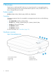
1 Overview The HP 560 is a dual band 802.11a/b/g/n/ac Access Point (AP). It is managed through its web-based management tool using Microsoft Internet Explorer 8 or later, Mozilla Firefox 17 or later, or Google Chrome 29 or later.
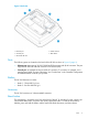
Figure 2 Back view 1. Ethernet port 4. Cable channel 2. Console port 5. Reset button 3. AP bracket tab slot Ports The following ports are located on the back of the HP 560 as shown in Figure 2 (page 5): • Ethernet port: Auto-sensing 10/100/1000 BaseT Ethernet port with RJ-45 connector. The port supports IEEE 802.3af and 802.3at Power over Ethernet (PoE). • Console port: A standard serial port with RJ-45 connector. To connect to a computer, use a standard serial cable.
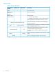
Status LEDs Table 1 AP status LED states Power/System OK LED Ethernet LED Radio1 LED Amber — — Flashing green every two seconds. — — Description The AP has power. The AP is starting up. Flashing green once per second. The AP is either: — — • Looking for an IP address • Building the list of VLANs on which to perform discovery The management tool is available until discovery occurs.
2 Installing the HP 560 The HP 560 is suited for indoor installation on a desktop, wall, ceiling, or in a plenum. The end user is responsible for ensuring that installation and use comply with local safety and radio regulations. IMPORTANT: This device requires professional installation.
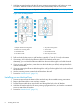
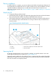
1. Hold the mounting bracket with the UP arrow pointing up against the wall where you want to install it. Mark the location of the screw holes (wall anchors) and the cutout area. NOTE: The holes that you use depend on the mounting surface. See Figure 3 (page 8). Figure 3 AP mounting bracket 2. 3. 1. Adapter bracket mounting holes 5. Drywall mounting holes 2. Electric box mounting holes 6. Cutout area 3. AP bracket latch 7. AP bracket lock tab 4. AP retention tabs 8.
Installing on a suspended ceiling Two sets of T-bar clips are included for installing the AP on a suspended ceiling: • If the ceiling tiles are recessed, use the 12.5 mm set of T-bar clips. • If the ceiling tiles are flush mount, use the 4.5 mm set of T-bar clips. WARNING! Areas above suspended ceilings can contain dangerous electrical cabling, gas pipes, and other hazards. Make whatever safety arrangements are needed to ensure that you can work safely above the false ceiling.
Plenum installation To install the device in a plenum, you must use plenum-rated cables and attachment hardware. HP recommends that you install the HP 560 in a similar orientation as in a ceiling installation. However, a qualified installer can determine how to install and secure the HP 560 in a plenum in an appropriate and safe manner. See “Plenum installation” (page 16) and “Installing on a suspended ceiling” (page 9). Attach the AP 1. 2. 3. Connect the Ethernet cable to the AP.
Figure 6 Retention screw and padlock bracket 1. AP bracket 4. Cable lock hole 2. Retention screw 5. AP padlock bracket 3. AP bracket lock tab 6. Padlock hole Removing the AP To remove the AP from the bracket: • Remove any locks and remove the retaining screw. 1.
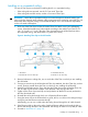
3 Controllers To become operational, the AP must establish a management tunnel with a controller. The controller manages the AP and provides all configuration settings. When power is applied, the AP establishes a connection to the controller automatically if default settings are used on the AP and the controller, and both devices are on the same subnet. No further configuration is required.
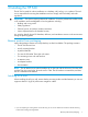
4 Support and other resources Contacting HP For worldwide technical support information, see the HP support website: http://www.hp.com/support Before contacting HP, collect the following information: • Product model names and numbers • Technical support registration number (if applicable) • Product serial numbers • Error messages • Operating system type and revision level • Detailed questions Related information The following documents provide related information: • HP 560 802.
Table 2 Document conventions (continued) Convention Element Monospace text • File and directory names • System output • Code • Commands, their arguments, and argument values Monospace, italic text • Code variables • Command variables Monospace, bold text WARNING! IMPORTANT: NOTE: 14 Emphasized monospace text Indicates that failure to follow directions could result in bodily harm or death. Provides clarifying information or specific instructions. Provides additional information.
5 Documentation feedback HP is committed to providing documentation that meets your needs. To help us improve the documentation, send any errors, suggestions, or comments to Documentation Feedback (docsfeedback@hp.com). Include the document title and part number, version number, or the URL when submitting your feedback.
A Regulatory information For important safety, environmental, and regulatory information, see Safety and Compliance Information for Server, Storage, Power, Networking, and Rack Products, available at http:// www.hp.com/support/Safety-Compliance-EnterpriseProducts. Plenum installation The device can be installed in a plenum.