
HP Fixed Cord Power Distribution Unit and Extension Bars Installation Instructions


HP Fixed Cord Power
Distribution Unit and
Extension Bars
Installation Instructions
Read Instructions Completely Before Beginning
Installation Procedures
© Copyright 2003 Hewlett-Packard Development Company, L.P.
The information contained herein is subject to change without notice. The
only warranties for HP products and services are set forth in the express
warranty statements accompanying such products and services. Nothing
herein should be construed as constituting an additional warranty. HP shall
not be liable for technical or editorial errors or omissions contained herein.
HP Fixed Cord Power Distribution Unit and Extension Bars Installation
Instructions
December 2003 (First Edition)
Part Number 351639-001
351639- 001
Audience Assumptions
This document is for the person who installs power products.
No installation or service procedure should be carried out by
someone other than a technician with specific experience with
high-voltage equipment. HP assumes you are qualified in the
servicing of high-voltage equipment and trained in recognizing
hazards in products with hazardous energy levels.
Overview
These instructions serve as an outline to assist qualified
personnel with the installation of this product.
The input voltage is either 100 to 120 VAC or 200 to 240 VAC,
depending on the model. This product consists of a control unit
with extension bars and is compatible with the HP 9000 and
10000 series racks.
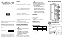
The control unit provides:
• Flexible mounting in 0U or 1U configurations, maximizing
rack space (no additional parts are required for mounting)
• Overcurrent and short-circuit protection for each output
(UL-489 listed circuit breakers)
• Manual On/Off control for each of the output load groups
• Pilot light for main AC input
• IEC-320 C19 outlets to power extension bars or other
IEC-320 C20 plug-compatible equipment
• Easy identification and reset of overload circuits (circuit
breakers move to Off position), minimizing downtime
• Switch guards to prevent inadvertent power-off
• Power cord retention
The extension bars provide:
• Simplified power distribution for fixed rail, 1U servers by
utilizing the extension bars with short, 33 cm (13 in),
attached cords
• Improved cable management and air flow
• Two installation brackets to accommodate applications
with either single-wide or dual power sources
Important Safety Information
Before installing this product, read the Important Safety
Information guide provided.
WARNING: To reduce the risk of personal
injury from electric shock, do not remove the cover.
There are no field-serviceable or user-serviceable
components inside.
WARNING: A risk of personal injury from
electric shock and hazardous energy levels exists.
The installation of options and routine maintenance
and service of this product must be performed by
individuals who are knowledgeable about the
procedures, precautions, and hazards associated with
AC power products.
Follow these safety precautions when connecting multiple
pieces of information technology equipment to power products.
WARNING: To reduce the risk of personal
injury from high-leakage current, verify earth
connection before connecting the power supply.
The summation of input power for multiple pieces of
information technology equipment through the use of
power products can result in high-leakage currents.
If the total system leakage current for a system of
components exceeds 3.5 mA:
• The use of a detachable input power cord is
prohibited.
• The input power cord must be securely attached
and it should be connected to the AC mains by
hardwiring or through the use of a non-residential,
industrial-style plug that maintains positive earth
connection.
• If the total system leakage current through the
ground conductor exceeds five percent of the
input current per line under normal operating
conditions, the system loads should be divided
among multiple power connections.
Kit Contents
Documentation
• Important Safety Information guide
• Warranty information
• This document
NOTE: This document is also available from the
reference library at http://www.hp.com.
Control Unit Hardware
• Control unit with an L6-30 plug
• Two 0U and two 1U mounting brackets
• One cord retention bracket
Extension Bar Hardware
Model Number of
Extension Bars
Number of
Single/Double
Brackets
Kit with control unit 4 8/4
Kit with extension
bars only
2 4/2
Tools Required
The following tools are required:
Phillips screwdrivers
HP Fixed Cord PDU and Extension
Bars
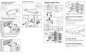
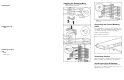
Installing the Cord Retention
Bracket
NOTE: If you ordered the fixed extension bars kit, skip to
the "Installing the Extension Bars" section of this
document.