SUPERSTACK® II ADVANCED RPS MANAGEMENT MODULE USER GUIDE 3C16080 Part No.
3Com Corporation ■ 5400 Bayfront Plaza ■ Santa Clara, California ■ 95052-8145 ©3Com Ireland 1997. All rights reserved. No part of this document may be reproduced in any form or by any means or used to make any derivative work (Such as translation, transformation, or adaptation) without permission from 3Com Ireland.
CONTENTS ABOUT THIS GUIDE Introduction Conventions v v 1 INTRODUCTION Networking Terminology 1-1 2 INSTALLATION The SuperStack II Advanced RPS Management Module Before You Start 2-2 Installing the Management Module 2-2 3 CONFIGURING THE MANAGEMENT MODULE Before You Start 3-1 Local Configuration 3-2 Command Line Interface 3-4 System Login 3-4 Commands 3-5 Changing the Configuration Fields 3-11 Software Update 3-13 Exiting the Configuration Program 3-14 4 MANAGING YOUR ADVANCED RPS Connecting to the Ne
A TECHNICAL SPECIFICATIONS Standards A-1 Physical Properties A-1 Console Port Pin Out A-2 MDI 10BaseT RJ-45 Connector Pin Out A-3 B TROUBLESHOOTING C TECHNICAL SUPPORT On-line Technical Services C-1 3Com Bulletin Board Service C-1 Access by Modem C-2 Access by ISDN C-2 World Wide Web Site C-3 ThreeComForum on CompuServe C-3 3ComFacts Automated Fax Service C-4 Support from Your Network Supplier C-5 Support from 3Com C-6 Returning Products for Repair C-7 LIMITED WARRANTY ELECTRO MAGNETIC COMPATABILITY STAT
ABOUT THIS GUIDE Introduction This guide describes how to install and use the SuperStack® II Advanced RPS Management Module. Each procedure is outlined in a series of steps. These procedures are written primarily for network supervisors who are responsible for installing and configuring the Management Module. You should also be familiar with PC hardware and software, and have a basic understanding of your network. Your network should be set up and operating properly.
vi ABOUT THIS GUIDE Convention Description “Enter” vs. “Type” When the word “enter” is used in this guide, it means to type something, then press the [Return] or [Enter] key. Do not press the [Return] or [Enter] key when the instruction simply says “type”.
1 INTRODUCTION In the modern business environment, communication and sharing information is crucial. With computer networks becoming larger and more complex, a constant power supply is vital to the operation of your organization. A Redundant Power Supply (RPS) provides a highly reliable resilient power supply to maintain network integrity. The SuperStack® II Advanced RPS Management Module provides network management of the Advanced RPS through monitoring and control.
1-2 CHAPTER 1: INTRODUCTION Simple Network Management Protocol (SNMP) is a protocol that controls how a management station gains information from a device. SNMP is composed of three areas: ■ A set of rules that define how a management station can communicate with a device. ■ A Management Information Base (MIB) that defines what information can be obtained from the device by the management station. Every SNMP-manageable device has a MIB.
2 INSTALLATION This chapter describes the SuperStack® II Advanced RPS Management Module and how to install the module in the SuperStack II Advanced RPS. The SuperStack II Advanced RPS Management Module The Management Module plugs directly into your SuperStack II Advanced RPS chassis. The Management Module connects to an Ethernet network with a 10BASE-T cable having an RJ-45 connector.
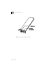
2-2 CHAPTER 2: INSTALLATION Figure 2-1 DUA1608-0AAA01 Ethernet Module Connections
Before You Start 2-3 Before You Start The SuperStack II Advanced RPS Management Module will only operate with the SuperStack II Advanced RPS. You will need a 10BASE-T cable for connection to your Ethernet network and a serial cable to configure your Management Module. You may also use the serial cable and for management via a modem, if required. Installing the Management Module To install the Management Module, you need access to the cables that are connected to your network.
2-4 CHAPTER 2: INSTALLATION Figure 2-2 Removing the Blanking Plate on Advanced RPS 2 Slide the Management Module into the open slot and secure with the screws provided. Make sure the RJ-45 connector is located on the lefthand side when looking at the rear panel.
3 CONFIGURING THE MANAGEMENT MODULE You need to configure the SuperStack ® II Advanced RPS Management Module before you can use it. The Management Module has a Command Line Interface (CLI) that you can access by connecting the module to a terminal or a computer with a terminal emulation program directly or via a modem. The CLI provides initial configuration of the Management Module. To manage the Superstack II Advanced RPS, you can use 3Com Transcend or another SNMP network manager.
3-2 CHAPTER 3: CONFIGURING THE MANAGEMENT MODULE You will only need to configure the addresses of the module if there is no configured BootP server on your network. To use the configuration program for the Management Module, you need: ■ A serial cable (see Table A-2 in Appendix A). ■ A terminal with an RS-232 serial port, or a PC with a terminal emulation program such as Windows Terminal®. The host serial port should be set to 9600 baud, no parity, 8 bits, and 1 stop bit.
Local Configuration 3-3 If you still do not see the login prompt, check the following conditions: ■ Check the communications settings of the terminal you are using. It should be set to 9600 baud, no parity, 8 bits, and 1 stop bit. ■ If the serial configuration is correct, check the cable between the module and terminal to be sure all connections are secure. ■ Make sure your terminal program is on the correct communications port for your RS-232 connection.
3-4 CHAPTER 3: CONFIGURING THE MANAGEMENT MODULE Command Line Interface The CLI allows configuration of the Management Module, for example assigning an IP address. It also allows recovery, in an emergency, to factory defaults. System Login To activate the CLI, press [Return]. You are presented with the title screen, showing the product name, the 3Com copyright and the software version number, and a login: prompt, as shown below: SuperStack II Advanced RPS Copyright © 3Com Ireland 1997.
Command Line Interface 3-5 Commands The available commands are described in more detail. Help Usage: help Abbreviation: ? or HE Description: Lists all of the available commands, as below: HElp IPAddress SUBnetmask TRApdestination DEFaultrouter SLIPAddress SLIPMask DEFaultrouter COMmunitystring FACTorydefaults DISplay PASSWD LOgout RESET FLOwctrl SWUpdate
3-6 CHAPTER 3: CONFIGURING THE MANAGEMENT MODULE Password Usage: PASSWD Abbreviation: None Description: Change the password for the current user. The CLI prompts you for the new password which, when typed in, is concealed by asterisks (*). You are prompted for the password twice before it is accepted. The minimum length of the password is 4 characters and the maximum length is 16 characters. Valid characters are; a to z, A to Z, and 0 to 9. If the password is lost, contact your supplier.
Command Line Interface Subnet Mask Usage: subnetmask a.b.c.d Abbreviation: SUB Description: Enters the Sub Net Mask for the device. Value takes effect from: Reset Command Value retained during Power cycle: Yes Default Router Usage: defaultrouter a.b.c.d Abbreviation: DEF Description: Enters the default router’s IP address.. Value takes effect from: Reset Command Value retained during Power cycle Yes SLIP Address Usage: DUA1608-0AAA01 slipaddress a.b.c.
3-8 CHAPTER 3: CONFIGURING THE MANAGEMENT MODULE SLIP Mask Usage: slipmask a.b.c.d Abbreviation: SLIPM Description: Enters the SLIP mask for the device. Value takes effect from: Reset Command Value retained during Power cycle: Yes Factory Defaults DUA1608-0AAA01 Usage: factorydefaults Abbreviation: FACT Description: Return the unit’s configuration to the factory defaults.
Command Line Interface 3-9 Flow Control Usage: FLOwctrl ON or OFF Abbreviation: FLO Description: Change the Console data flow signal to ON or OFF. The default is OFF. When enabled, the modem control signals are enabled (see Appendix A) along with XON and XOFF. If the DSR signal goes low when in the enabled state, the Management Module automatically logs you out.
3-10 CHAPTER 3: CONFIGURING THE MANAGEMENT MODULE Reset Usage: RESET Abbreviation: None. Description: Resets the Management Module. Any changed network parameters are then implemented as described previously. You are automatically logged-out of the system during the reset. Value retained during Power cycle: No Trap Destination Usage: trapdestination a.b.c.d Abbreviation: TRA Description: Enters the Trap destination address for the device.
Command Line Interface 3-11 Changing the Configuration Fields The first fields you must configure depend on the method of network connection that you are using. For Ethernet, you need to configure the IP address, Subnet mask and Default Router. For SLIP, you need to configure the SLIP address and SLIP mask. To change the value of a setup option, enter the command (or abbreviation) followed by the new value. If you enter a command without a new value or an invalid value, an error message is displayed.
3-12 CHAPTER 3: CONFIGURING THE MANAGEMENT MODULE Subnet Mask To change the Subnet mask value, type SUB followed by a space and the Subnet mask value. Use the format a.b.c.d, where a, b, c and d are numbers between 0 and 255. If you type a number that is not in this range, an error message appears. If your local network is partitioned into subnets, be sure to set this value to show that (for example, 255.255.0.0). The default Subnet mask is 0.0.0.0 .
Command Line Interface 3-13 SLIP Address To change the SLIP address, type SLIPA followed by a space and the SLIP address assigned to the Management Module. Use the format a.b.c.d, where a, b, c and d are numbers between 0 and 255. If you type a number that is not in this range, an error message appears. The default SLIP address is 192.168.101.2. If you do not know the SLIP address to use, contact your network administrator. Press [Enter] to save the new setting.
3-14 CHAPTER 3: CONFIGURING THE MANAGEMENT MODULE The default Trap address is 0.0.0.0, which disables Traps. Any change to the default results in Traps being sent to the newly specified Trap address. To change the Trap destination, type TRA followed by a space and the new address for the Traps. This should be the IP address of your Network Management Station. Use the format a.b.c.d, where a, b, c and d are numbers between 0 and 255. If you type a number that is not in this range, an error message appears.
4 MANAGING YOUR ADVANCED RPS Be sure you have the appropriate cables and connectors, as described in “Before You Start” on page 2-3. Connecting to the Network To connect the Management Module to the network: 1 Plug one end of a twisted-pair cable into the RJ-45 port on the Management Module. 2 Plug the other end into an appropriate port on your network device.
4-2 CHAPTER 4: MANAGING YOUR ADVANCED RPS Managing Your Advanced RPS For day-to-day management of the SuperStack® II Advanced RPS system, we recommend Transcend Enterprise Manager. For more details on this and other products, please contact your supplier.
TECHNICAL SPECIFICATIONS A Standards The SuperStack® II Advanced RPS Management Module has been designed to comply with the following standards: Safety UL 1950 CSA C22.2.-950 EN 60950 EMC EN 55022 FCC Part 15 CSA C108-8 EN 50082-1 VCCI AS/NZS 3548 Class B* Class A Class A Class 2* Class B* Environmental EN 60068 * Category 5 shielded cables are required to meet the Class B limits of this standard. The use of unscreened cables (category 3 or 5) complies with the Class A limits.
A-2 Appendix A: Technical Specifications Console Port Pin Out Table A-2 Console Port Pin Out Pin Number Signal 1 DCD 2 RD 3 TD 4 DTR 5 Ground 6 DSR 7 RTS 8 CTS 9 No connection Figure A-1 Console Port Numbering The console port has the same configuration as an IBM PC Com port. Only the TD, RD and ground pins need be connected to use the CLI from a terminal.
MDI 10BASE-T RJ-45 Connector Pin Out A-3 MDI 10BASE-T RJ-45 Connector Pin Out Table A-3 RJ-45 Connector Pin Out Contact MDI Signal 1 TD+ 2 TD- 3 RD+ 4 No connection 5 RD- 6 No connection 7 No connection 8 No connection Figure A-2 RJ-45 Connector Numbering DUA1608-0AAA01
A-4 Appendix A: Technical Specifications Cabling 10BASE-T Cabling Figure A-3 10BASE-T Cabling Serial Cable Figure A-4 Pin Numbering for Serial Cable DUA1608-0AAA01
Cabling A-5 Examples of null modem cables you can use follow.
A-6 Appendix A: Technical Specifications DUA1608-0AAA01
B TROUBLESHOOTING Use the following troubleshooting chart to help you solve any problems that may occur with the SuperStack® II Advanced RPS Management Module. Problem Possible Cause Corrective Action The Management Module does not initialize Bad cable connection Verify cable connections at the Management Module Login prompt does not appear Incorrect cable. Replace cable. Bad cable connections Check security of connection. Replace cable if required.
B-2 APPENDIX B: TROUBLESHOOTING DUA1608-0AAA01 Problem Possible Cause Corrective Action Management Module does not respond to SNMP Get requests, but does respond to Pings. Wrong community namestring being used. The Get-community name community strings that wasere set during the module configuration does not match the ones being used by your network management system (NMS) for Get requests.
TECHNICAL SUPPORT C 3Com provides easy access to technical support information through a variety of services. This appendix describes these services. Information contained in this appendix is correct at the time of publication. For the very latest details, we recommend you access 3Com Corporation’s World Wide Web site as described below.
C-2 APPENDIX C: TECHNICAL SUPPORT Country Data Rate Telephone Number Australia Up to 14400 bps (61) (2) 9955 2073 France Up to 14400 bps (33) (1) 01 69 86 69 54 Germany Up to 9600 bps (49) (89) 627 32 188 or (49) (89) 627 32 189 Hong Kong Up to 14400 bps (852) 537 5608 Italy (fee required) Up to 14400 bps (39) (2) 273 00680 Japan Up to 14400 bps (81) (3) 3345 7266 Singapore Up to 14400 bps (65) 534 5693 Taiwan Up to 14400 bps (886) (2) 377 5838 U.K.
On-line Technical Services C-3 To use 3ComForum: 1 Log on to CompuServe. 2 Enter go threecom. 3 Press [Return] to see the Ask3ComForum main menu. 3ComFacts Automated Fax Service 3Com Corporation’s interactive fax service, 3ComFacts, provides data sheets, technical articles, diagrams, and troubleshooting instructions on 3Com products 24 hours a day, seven days a week. Call 3ComFacts using your touch-tone telephone. International access numbers are: Country Fax Number Hong Kong (852) 2537 5610 U.K.
C-4 APPENDIX C: TECHNICAL SUPPORT Support from Your Network Supplier If additional assistance is required, contact your network supplier. Many suppliers are authorized 3Com service partners who are qualified to provide a variety of services, including network planning, installation, hardware maintenance, application training and support services.
Returning Products for Repair C-5 Canada (416) 498 3266 Singapore (65) 538 9368 Denmark* 800 17309 South Africa (27) (11) 803 7404 Finland* 0800 113153 Spain* (34) (1) 3831700 France* 05 917959 Sweden* (45) (8) 632 91 00 Germany* 0130 821502 Taiwan (886) (2) 577 4352 Hong Kong (852) 868 9111 United Arab Emirates (971) (4) 349049 Ireland* 1 800 553117 U.K.* 0800 966197 Italy* 1678 79489 U.S.
C-6 APPENDIX C: TECHNICAL SUPPORT DUA1608-0AAA01
Limited Warranty HARDWARE: 3Com warrants its hardware products to be free from defects in workmanship and materials, under normal use and service, for the following lengths of time from the date of purchase from 3Com or its Authorized Reseller: Internetworking products One Year Network adapters Lifetime Ethernet stackable hubs and Unmanaged Ethernet fixed port repeaters *Power supply and fans in these stackable hubs and unmanaged repeaters Lifetime* (One Year if not registered) One Year Other hardware
STANDARD WARRANTY SERVICE: Standard warranty service for hardware products may be obtained by delivering the defective product, accompanied by a copy of the dated proof of purchase, to 3Com’s Corporate Service Center or to an Authorized 3Com Service Center during the applicable warranty period. Standard warranty service for software products may be obtained by telephoning 3Com’s Corporate Service Center or an Authorized 3Com Service Center, within the warranty period.
FEDERAL COMMUNICATIONS COMMISSION RADIO AND TELEVISION INTERFERENCE STATEMENT FOR CLASS A DEVICES This equipment has been tested and found to comply with the limits for Class A digital devices, pursuant to part 15 of the FCC Rules. These limits are designed to provide reasonable protection against harmful interference in a residential installation.