ProCurve Switches ProCurve 5400zl Series 6120 Blade Switches Installation and Getting Started Guide Installation and Getting Started Guide
© Copyright 2009, 2011 Hewlett-Packard Development Company, L.P. Publication Number 5992-5445 September 2011 Applicable Products: HP ProCurve 6120G/XG Blade Switch HP ProCurve 6120XG Blade Switch Disclaimer HEWLETT-PACKARD COMPANY MAKES NO WARRANTY OF ANY KIND WITH REGARD TO THIS MATERIAL, INCLUDING, BUT NOT LIMITED TO, THE IMPLIED WARRANTIES OF MERCHANTABILITY AND FITNESS FOR A PARTICULAR PURPOSE.
Contents Introducing the Switch . . . . . . . . . . . . . . . . . . . . . . . . . . . . . . . . . . . . . . . . . . . . . 1 HP ProCurve 6120G/XG Blade Switch . . . . . . . . . . . . . . . . . . . . . . . . . . . . . 1 HP ProCurve 6120XG Blade Switch . . . . . . . . . . . . . . . . . . . . . . . . . . . . . . . 4 Dual-personality ports . . . . . . . . . . . . . . . . . . . . . . . . . . . . . . . . . . . . . . 6 Pre-Installation Planning . . . . . . . . . . . . . . . . . . . . . . . . . . . . . . . . . . . .
Diagnosing the 6120G/XG with the LEDs . . . . . . . . . . . . . . . . . . . . . . . . . . . . . 24 Diagnostic Tips: . . . . . . . . . . . . . . . . . . . . . . . . . . . . . . . . . . . . . . . . . . . . . . 25 Diagnosing the 6120XG with the LEDs . . . . . . . . . . . . . . . . . . . . . . . . . . . . . . . 27 Diagnostic Tips: . . . . . . . . . . . . . . . . . . . . . . . . . . . . . . . . . . . . . . . . . . . . . . 27 Proactive Networking . . . . . . . . . . . . . . . . . . . . . . . . . . . . . . . . . .
Straight-Through Twisted-Pair Cable for 10 Mbps or 100 Mbps Network Connections . . . . . . . . . . . . . . . . . . . . . . . 42 Cable Diagram . . . . . . . . . . . . . . . . . . . . . . . . . . . . . . . . . . . . . . . . . . . 42 Pin Assignments . . . . . . . . . . . . . . . . . . . . . . . . . . . . . . . . . . . . . . . . . . 42 Crossover Twisted-Pair Cable for 10 Mbps or 100 Mbps Network Connection . . . . . . . . . . . . . . . . . . . . . . . . 43 Cable Diagram . . . . . . . . . . . . . . . . . . . .
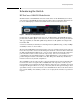
Introducing the Switch Introducing the Switch HP ProCurve 6120G/XG Blade Switch The HP ProCurve 6120G/XG Blade Switch is a blade switch for the HP BladeSystem c-Class enclosures. The 6120G/XG Blade Switch supports advanced layer 2 switching. This switch can be used to build high speed switched networks between servers in the data center. Figure 1.
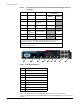
Introducing the Switch Table 1.
Introducing the Switch ➊ ➋ ➌ ➍ ➎ ➏ ➐ ➑ ➒ ➓ 11 Figure 3.
Introducing the Switch HP ProCurve 6120XG Blade Switch The HP ProCurve 6120XG Blade Switch is a blade switch for the HP BladeSystem c-Class enclosures. The 6120XG Blade Switch supports advanced Layer two switching. This switch can be used to build high speed switched networks between servers in the data center. Figure 4. HP ProCurve 6120XG Blade Switch Designed for the c-Class BladeSystem enclosure, the HP ProCurve 6120XG Blade Switch provides one 10GBASE-CX4 port and eight SFP+ (10-GbE) uplinks.
Introducing the Switch Table 2.
Introducing the Switch ➊ ➋ ➌ ➍ ➎ ➏ ➐ ➑ ➒ ➓ 11 12 Figure 5. Blade Switch components Item Description 1 Port 17 (10GBASE-CX4)1 2 Console Port (USB 2.
Introducing the Switch ➊ ➋ ➌ ➎ ➍ ➓ ➏ ➒ ➑ ➐ Figure 6.
Pre-Installation Planning Pre-Installation Planning Before beginning installation complete the following tasks: ■ It is recommended the firmware revisions on all ProCurve Blade Switches are at the same revision level. Some versions of the firmware might not be compatible. ■ Determine which mezzanine cards, HBAs, and interconnect Switches are going to be used and where they will be installed in the enclosure.
Switch Installation Switch Installation Installation guidelines Observe the following guidelines: ■ To support a redundant configuration for the Blade Switch, install a second Blade Switch of the same type in an adjacent bay. ■ To avoid connectivity loss, do not install different types of Blade Switches in interconnect bays connected to the same server blade mezzanine card.
Switch Installation Note 2. Prepare the Blade Switch for installation. 3. Install the Blade Switch into the interconnect bay. 4. If the enclosure configuration includes more than one Blade Switch, install the other Blade Switches now. 5. Connect the data center network cables to any Blade Switch port not being used. The 1000BASE-SFP, 10GBASE-XFP, and 10-GbE SFP+ ports can be used to connect to the data center if they are populated with a supported pluggable SFP, XFP, or SFP+ optical transceiver.
Switch Installation Accessing the Blade Switch from the HP BladeSystem Onboard Administrator These instructions assume that you have already set up the HP BladeSystem Onboard Administrator (OA) using the First Time Setup Wizard. See the HP BladeSystem Onboard Administrator User Guide for details on OA setup. For information on OA command line interface (CLI) commands, see the HP BladeSystem Onboard Administrator Command Line Interface User Guide. Both guides are available at www.hp.
Switch Installation ■ ■ OnBoard Administrator: • (preferred) Through the enclosure manager as described on page 11, “Accessing the Blade Switch from the HP BladeSystem Onboard Administrator” • Telnet to the out-of-band management port IP address. This is the IP address described on page 8. In-Band: Access the console using Telnet from a PC or UNIX station on the network, and a VT-100 terminal emulator.
Switch Installation 4. Connect the standard end of the supplied USB console cable to a workstation or laptop computer. The computer will recognize the presence of a new USB device and load the driver for it. 5. Using a terminal program (such as HyperTerminal or TeraTerm), open a connection to the USB port. (By default this port will appear as COM4.) 6. Press Enter twice. The blade switch CLI prompt appears. You are now ready to enter blade switch commands.
Switch Installation Installing a mini-GBIC, SFP+ or XFP transceiver 1. Remove the dust cap and save it for future use. 2. Install the transceiver with the label side up. Ensure the latch is closed and the transceiver is fully seated. Figure 8. Inserting a transceiver Removing a mini-GBIC Note Removing and installing a transceiver can shorten the useful life. Do not remove and insert transceivers more often than is necessary. 1. Disconnect all cables. 2. Open the latch and remove the transceiver.
Switch Installation Example Topologies The following illustrations are examples of typical, supported configurations for an HP BladeSystem c3000 and BladeSystem c7000 Enclosure. Top of rack switch Server with one 6120G/XG Blade Switch 6120G/XG Blade Switch Figure 10. Example single point topology This illustration shows the most basic of configurations.
Switch Installation Top of rack switches Server with two 6120G/XG Blade Switches 6120G/XG Blade Switch Figure 11. Example high availability topology Note Install identical ProCurve 6120 switches in adjacent interconnect bays to support high availability. See figure 11. Installing the Blade Switches in adjacent interconnect bays (as shown in Figure 8) allows for the opportunity to enable the ISL(s). The 6120G/XG has one ISL and the 6120XG has two ISLs.
Switch Installation Gigabit fiber cable ProCurve Switch 6600 Servers Servers Gigabit fiber cable ProCurve Switch 6600 Servers Servers Figure 12.
Getting Started With Switch Configuration Getting Started With Switch Configuration This section is a guide for using the console Switch Setup screen to quickly assign an IP (Internet Protocol) address and subnet mask to the switch, set a Manager password, and, optionally, configure other basic features.
Using the Console Setup Screen Using the Console Setup Screen The quickest and easiest way to minimally configure the switch for management and password protection in your network is to use the OA. 1. Either use the OA connect command to connect to the switch’s console see “Accessing the Blade Switch from the HP BladeSystem Onboard Administrator” on page -11. or telnet to the IP address assigned by the enclousure bay addressing, see “Hardware setup overview” on page -8.
Where to Go From Here Table 3. Setup screen fields Parameter Default System Name blank Optional; up to 25 characters, including spaces System Contact blank Optional; up to 48 characters, including spaces Manager Password blank Recommended; up to 16 characters (no blank spaces) Logon Default CLI The default setting selects the command line interface for console access. The alternative is the menu interface. Time Zone 0 (none) Optional; 1440 to -1440.
Using the IP Address for Remote Switch Management Using the IP Address for Remote Switch Management The switch’s IP address can be used to manage the switch from any PC on the same subnet as the switch. Either a Telnet session or a standard web browser can be used to manage the switch. Starting a Telnet Session To access the switch through a Telnet session, follow these steps: 1.
Troubleshooting The following illustration shows a typical web browser interface screen. For more information on using the web browser interface, see the Management and Configuration Guide for the Series 6120 Switches, which is on the ProCurve Web site at www.hp.com/go/bladesystem/documentation. An extensive help system is also available for the web browser interface.
Basic Troubleshooting Tips Basic Troubleshooting Tips Most problems are caused by the following situations. Check for these items first when starting your troubleshooting: ■ Connecting to devices that have a fixed full-duplex configuration. The RJ-45 ports are configured as “Auto”.
Basic Troubleshooting Tips ■ Check the port configuration. A port on your switch may not be operating as you expect because it has been put into a “blocking” state by Spanning Tree, GVRP (automatic VLANs), or LACP (automatic trunking). (Note the normal operation of the Spanning Tree, GVRP, and LACP features may put the port in a blocking state.) Or, the port just may have been configured as disabled through software. Other switch features that may affect the port operation include VLANs and IGMP.
Diagnosing the 6120G/XG with the LEDs Diagnosing the 6120G/XG with the LEDs Table 3 shows LED patterns on the switch blade that indicate problem conditions. 1. Check in the table for the LED pattern you see on your switch. 2. Refer to the corresponding diagnostic tip on the next few pages.
Diagnosing the 6120G/XG with the LEDs Tip Problem Solution ➌ The network connection is not working properly. Try the following procedures: • Verify the transceiver is of a supported type. • Verify the OA port configurations for the downlink ports to the server are correct. • For the indicated port, verify both ends of the cabling, at the switch and the connected device, are connected properly. • Verify the connected device and switch are both powered on and operating correctly.
Diagnosing the 6120XG with the LEDs Diagnosing the 6120XG with the LEDs Table 5 shows LED patterns on the switch blade that indicate problem conditions. 1. Check in the table for the LED pattern you see on your switch. 2. Refer to the corresponding diagnostic tip on the next few pages.
Diagnosing the 6120XG with the LEDs Tip Problem Solution ➌ The network connection is not working properly. Try the following procedures: • Verify the transceiver is of a supported type. • Verify the OA port configurations for the downlink ports to the server are correct. • For the indicated port, verify both ends of the cabling, at the switch and the connected device, are connected properly. • Verify the connected device and switch are both powered on and operating correctly.
Proactive Networking Proactive Networking The ProCurve Blade Switches have built-in management capabilities that proactively help you manage your network including: ■ finding and helping you fix the most common network error conditions (for example, faulty network cabling, and non-standard network topologies) ■ informing you of the problem with clear, easy-to-understand messages ■ recommending network configuration changes to enhance the performance of your network The following interfaces provide te
Hardware Diagnostic Tests ■ All green for one second ■ All off except for the Health LED and any activity LEDs. See “Diagnosing With the LEDs” on page 25 for information on interpreting the LED patterns and LED behaviors. Checking Console Messages Useful diagnostic messages may be displayed on the console screen when the switch is reset.
Restoring the Factory Default Configuration Restoring the Factory Default Configuration As part of your troubleshooting process on the switch, it may become necessary to return the switch configuration to the factory default settings.
Restoring the Factory Default Configuration Switch system maintenance switch 1 Switch Default Function 1 Off1 On = Boot to ROM 2 Off Reserved 3 Off Reserved 4 Off Reserved Normal operation is off. The Switch system maintenance switch is used for redirecting the switch to boot either to ROM prompt or boot to the system image. To change the boot function follow these steps: 1. Remove the switch from the enclosure. 2. Set dip-switch 1 to ON to turn system image boot off. 3.
Restoring the Factory Default Configuration Restoring Factory Firmware This feature is built into the boot ROM, and it provides a way to recover from a situation where both primary and secondary images are not bootable. Since the xmodem download will not work on the 6120XG or the 6120G/XG switch, this is the mechanism to use in case both images are not bootable. Required user action is highlighted.
Downloading New Switch Software Recovering... -- Download for this Product, proceeding -pass CRC check (len=7641083) , Erasing 59 segments..., Programming starting at 0xf8000000... programming successful... Ready for code execution. Decompressing...done. Answer the following questions: Switch startup, use Debugger (y or n)? N initializing..initialization done. Hit enter to Continue.
HP Customer Support Services Before Calling Support Before calling your contacting Support, to make the support process most efficient, you first should have retrieved the following information: • Product identification, including product serial number, product name and number, and include any XFPs and mini-GBICs.
Specifications Specifications Physical 6120G/XG 6120XG Width: 92.79 mm (7.5 in) 92.79 mm (7.5 in) Depth: 267.7 mm (10.5 in) 267.7 mm (10.5 in) Height: 27.94 mm (1.1 in) 27.94 mm (1.1 in) Weight: 1.27 kg (2.8 lbs) 1.27 kg (2.8 lbs) Environmental Operating Non-Operating Temperature: 10C to 35C (50F to 95F) -20C to 60C (-4F to 140F) Relative humidity: (non-condensing) 10% to 90% 10% to 95% Maximum altitude: 3.0 km (10,000 ft) 4.
Specifications Lasers The following products are Class 1 Laser Products. Laser Klasse 1: ■ The SFP SR transceiver ■ The SFP LR transceiver ■ The XFP transceivers ■ The SFP+ SR transceiver ■ The SFP+ LR transceiver The transceivers comply with IEC 60825. Table 6. Technology standards and safety compliance Laser safety information Technology Compatible with these IEEE standards EN/IEC standard compliance SFP ("mini-GBIC") Lasers SFP+ Lasers XFP Lasers 10/100/1000-T IEEE 802.
Cabling and Technology Information Cabling and Technology Information This section includes network cable information for cables that should be used with the Switch, including minimum pin-out information and specifications for twisted-pair cables. Note Incorrectly wired cabling is the most common cause of problems for LAN communications. ProCurve recommends that you work with a qualified LAN cable installer for assistance with your cabling requirements. Cabling specifications Table 7.
Cabling and Technology Information Technology distance specifications Table 8.
Cabling and Technology Information To network multimode cabling Mode Conditioning Patch Cord The multimode cable in the patch cord must match the characteristics of your network cable Figure 9. Tx Gigabit-LX port Rx If you connect the patch cord directly to the network cabling, you may need to install a femaleto-female adapter to allow the cables to be connected together.
Cabling and Technology Information Straight-Through Twisted-Pair Cable for 10 Mbps or 100 Mbps Network Connections Because of the HP Auto-MDIX operation of the 10/100 ports on the switch, for all network connections, to PCs, servers or other end nodes, or to hubs or other switches, you can use straight-through cables.
Cabling and Technology Information Crossover Twisted-Pair Cable for 10 Mbps or 100 Mbps Network Connection The HP Auto-MDIX operation of the 10/100 ports on the switch also allows you to use crossover cables for all network connections, to PCs, servers or other end nodes, or to hubs or other switches.
Cabling and Technology Information Straight-Through Twisted-Pair Cable for 1000 Mbps Network Connections 1000Base-T connections require that all four pairs or wires be connected. Cable Diagram Note Pins 1 and 2 on connector “A” must be wired as a twisted pair to pins 1 and 2 on connector “B”. Pins 3 and 6 on connector “A” must be wired as a twisted pair to pins 3 and 6 on connector “B”. Pins 4 and 5 on connector “A” must be wired as a twisted pair to pins 4 and 5 on connector “B”.
Safety and EMC Regulatory Statements Safety and EMC Regulatory Statements Safety Information ! Documentation reference symbol. If the product is marked with this symbol, refer to the product documentation to get more information about the product. WARNING A WARNING in the manual denotes a hazard that can cause injury or death. Caution A Caution in the manual denotes a hazard that can damage equipment.
Safety and EMC Regulatory Statements Informations concernant la sécurité ! Symbole de référence à la documentation. Si le produit est marqué de ce symbole, reportezvous à la documentation du produit afin d'obtenir des informations plus détaillées. WARNING Dans la documentation, un WARNING indique un danger susceptible d'entraîner des dommages corporels ou la mort. Caution Un texte de mise en garde intitulé Caution indique un danger susceptible de causer des dommages à l'équipement.
Safety and EMC Regulatory Statements Hinweise zur Sicherheit ! Symbol für Dokumentationsverweis. Wenn das Produkt mit diesem Symbol markiert ist, schlagen Sie bitte in der Produktdokumentation nach, um mehr Informationen über das Produkt zu erhalten. WARNING Eine WARNING in der Dokumentation symbolisiert eine Gefahr, die Verletzungen oder sogar Todesfälle verursachen kann. Caution Caution in der Dokumentation symbolisiert eine Gefahr, die dis Gerät beschädigen kann.
Safety and EMC Regulatory Statements Considerazioni sulla sicurezza ! Simbolo di riferimento alla documentazione. Se il prodotto è contrassegnato da questo simbolo, fare riferimento alla documentazione sul prodotto per ulteriori informazioni su di esso. WARNING La dicitura WARNINGdenota un pericolo che può causare lesioni o morte. Caution La dicituraCaution denota un pericolo che può danneggiare le attrezzature.
Safety and EMC Regulatory Statements Consideraciones sobre seguridad ! Símbolo de referencia a la documentación. Si el producto va marcado con este símbolo, consultar la documentación del producto a fin de obtener mayor información sobre el producto. WARNING Una WARNING en la documentación señala un riesgo que podría resultar en lesiones o la muerte. Caution Una Caution en la documentación señala un riesgo que podría resultar en averías al equipo.
Safety and EMC Regulatory Statements Safety Information (Japan) Japan Power Cord Warning 49
Safety and EMC Regulatory Statements Safety Information (China) 50
EMC Regulatory Statements EMC Regulatory Statements U.S.A. FCC Class A This equipment has been tested and found to comply with the limits for a Class A digital device, pursuant to Part 15 of the FCC Rules. These limits are designed to provide reasonable protection against interference when the equipment is operated in a commercial environment.
European Community DECLARATION OF CONFORMITY according to ISO/IEC 17050-1 and EN 17050-1 DoC #: HSTNS-BC13-N-R2 Hewlett-Packard Company 11445 Compaq Center Drive West, Houston, TX 77070 USA Supplier's Name: Supplier's Address: declares, that the product Product Name and Model: 2) Regulatory Model Number: 1) Product Options: HP 1/10 Gb Virtual Connect Ethernet Module for c-Class Blade Systems / HP ProCurve 6120G/XG Blade Switch HSTNS-BC13-N All conforms to the following Product Specifications and Regu
EMC Regulatory Statements China Regulatory Statements ᳝↦ǃ᳝ᆇ⠽䋼/ܗ㋴ঞ݊䞣㸼 ձ✻Ё lj⬉ᄤֵᙃѻક∵ᶧࠊㅵ⧚ࡲ⊩NJ ᳝↦ǃ᳝ᆇ⠽䋼ܗ㋴ 䚼ӊৡ⿄ 䪙 (Pb) ∲ (Hg) 䬝 (Cd) ݁Ӌ䫀 (Cr(VI)) ⒈㘨㣃 (PBB) ⒈ҷѠ㣃䝮 3%'( ᴎㆅ/䱨ᵓ/݊ᅗ䞥 ሲล᭭䚼ӊ 0 0 0 0 0 0 ॄࠋ⬉䏃㒘ӊ (PCA) X 0 0 0 0 0 㒓 X 0 0 0 0 0 ⬉㓚/⬉㒓 X 0 0 0 0 0 ⬉∴ 0 0 0 0 0 0 亢/亢Ⲭ 0 0 0 0 0 0 ⬉⑤/⬉⑤䗖䜡఼ X 0 0 0 0 0 ᅝ㺙ᬃᶊ/݊ᅗ䰘 ӊ 0 0 0 0 0 0 CF व 0 0 0 0 0 0 2 㸼⼎ℸ䚼ӊՓ⫼ⱘ᠔᳝ৠ㉏ᴤ᭭Ёℸ⾡᳝↦᳝ᆇ⠽䋼ⱘ䞣ഛԢѢ
ProCurve 5400zl Switches Installation and Getting Startd Guide Technology for better business outcomes To learn more, visit www.hp.com/go/bladesystem © Copyright 2009, 2011 Hewlett-Packard Development Company, L.P. The information contained herein is subject to change without notice. The only warranties for HP products and services are set forth in the express warranty statements accompanying such products and services. Nothing herein should be construed as constituting an additional warranty.