
Opacity Shield Kit (JG557A) FIPS Enclosure Installation Guide

Introduction to the opacity shield kit
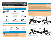
Installation tools
The installation tools are not provided with the switch. Prepare them yourself.
Phillips screwdriver
ESD-preventive
wrist strap
Spanner
Applicable products
HP 5120-24G EI Switch with 2 Interface Slots (JE068A)
HP 5120-48G EI Switch with 2 Interface Slots (JE069A)
HP 5500-24G EI Switch with 2 Interface Slots (JD377A)
HP 5500-48G EI Switch with 2 Interface Slots (JD375A)
Alcohol-based
cleaning pad
M3 countersunk-head screw (3
for the left-side opacity shield
and 1 for the rear opacity shield)
Tamper evidence label
(30 in total)
Left-side opacity shield
(1 in total)
Rear opacity shield
(1 in total)
M3 hex bolt A
(1 for the rear opacity shield)
M4 pan-head screw
(1 for the rear opacity shield)
M4 hex bolt A (2 for the
left-side opacity shield)
M4 hex bolt B
(1 for the rear opacity shield)
M3 hex bolt B
(1 for the left-side opacity shield)
HP 5120 EI and 5500 EI switches meet the requirement of FIPS security level 2.
Installing the opacity shields
The methods for installing the opacity shields to the applicable products are the same.
This section uses an HP 5120-24G EI Switch with 2 Interface Slots as an example.
Only use the screws and hex bolts that are supplied in the opacity shield kit to secure the
opacity shield.
Remove the screws, if any, on the chassis where the opacity shields are to be installed
before installing the opacity shields.
Preparing for installation
The installation procedures must be performed by qualified personnel.
Before installation, read the Compliance and Safety Manual for the compatible switch of
the opacity shield kit.
Make sure the operating temperature is not higher than 40°C (104°F).
Wear an ESD-preventive wrist strap, and make sure the wrist strap makes good skin
contact and is well grounded.
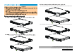
HP recommends that you install the front mounting brackets before installing the opacity shields.
The front mounting brackets installed at the power supply side
The front mounting brackets installed at the port side
M4 pan-
head screw
Ring terminal
M3 countersunk-
head screw
M3 hex
bolt A
M4 hex bolt B
M3 countersunk-
head screw
M4 hex bolt A
M3 hex
bolt B
M3 countersunk-
head screw
M4 hex
bolt A
M3 hex
bolt A
M3 countersunk-
head screw
M4 hex bolt B
M4 pan-head
screw
Ring terminal
M3 hex bolt B