
Opacity Shield Kit (JG558A) FIPS Enclosure Installation Guide
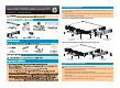

Installing the opacity shields
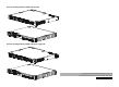
Applying tamper evidence labels
Make sure the chassis temperature is above 10°C (50°F).
Before applying tamper evidence labels, use alcohol-based cleaning pads to clean the
chassis and air dry the cohesive areas.
Apply tamper evidence labels to all field replacement units
(for example, opacity shields, interface cards, and power supplies), and any screw on an
opacity shield.
If the switch is to be installed on a rack, HP recommends that you apply tamper
evidence labels before installing the switch to the rack.
The front mounting brackets installed at the power supply side
The front mounting brackets installed at the port side
M3 countersunk-
head screw
M3 countersunk-
head screw
M3 hex bolt A M4 hex bolt
M3 countersunk-
head screw
M3 countersunk-
head screw
M4 hex boltM3 hex bolt
Only use the screws and hex bolts that are supplied in the opacity shield kit to secure the
opacity shield.
Remove the screws, if any, on the chassis where the opacity shields are to be installed
before installing the opacity shields.